Esse-ti 4G.VoLTE Bedienungsanleitung

03/04/2023 7IS-80575
User’s manual

TABLE OF CONTENTS
GENERAL INSTALLATION INSTRUCTIONS..............................4
General Notes.................................................................................4
Making the installation...................................................................4
DESCRIPTION..................................................................................5
Features.................................................................................................6
LEDs .....................................................................................................7
Hardware description.............................................................................8
INSTALLATION...............................................................................9
Inserting the SIM card...........................................................................9
Connecting the antenna..........................................................................9
Connection to the telephone line..........................................................10
Intercom connection............................................................................10
Connection to the power supply ..........................................................11
Turning the gateway on.......................................................................12
Gateway mounting operations.............................................................13
Installation recommendations..............................................................13
PROGRAMMING............................................................................14
Programming by telephone..........................................................14
(1) SIM card expiration check ...............................................................21
(2) Battery check ...................................................................................21
(3) External power failure check............................................................22
(4) Relay-based notification of external power failure and/or mobile
network loss.........................................................................................22
(5) Periodic test......................................................................................23
(6) Automatic converter of selected telephone number..........................23
Programming via SMS.................................................................26
Message format ...................................................................................26
Notification message format................................................................29
SERVICES.......................................................................................30
Incoming calls..............................................................................30
Outgoing calls..............................................................................30
Intercom.......................................................................................31
Measuring the signal level ...........................................................31
Reading the days missing to SIM card expiration........................32

Reading the battery status ............................................................33
Relay use......................................................................................33
Activation/Deactivation.......................................................................33
Pulse....................................................................................................34
Reading advanced device and radio cell parameters ....................35
SMS/DTMF CONVERTeR..............................................................36
Notification message ...........................................................................37
SIGNALS.........................................................................................39
Tones............................................................................................39
Call signals...................................................................................40
LEDs............................................................................................41
4G LTE/UMTS/GSM signal indicator LED (GREEN) .......................41
Device status indicator LED (RED).....................................................42
Line status indicator LED (WHITE)....................................................42
Power supply status indicator LED (BLUE)........................................43
TROUBLE SHOOTING GUIDE.....................................................44
FREQUENCIES...............................................................................45
EU DECLARATION OF CONFORMITY......................................46

Page 4
GENERAL INSTALLATION
INSTRUCTIONS
GENERAL NOTES
Carefully read the notes contained in this section as they provide important
information on safe correct installation, use and maintenance of the product.
•The product must be EXCLUSIVELY used for the purpose it was designed for.
Esse-ti shall not be responsible for damages arising from improper use.
•The product has been designed in compliance with the regulations in force and
must be installed in systems that comply with the provisions of law.
•Always disconnect power supply before performing internal or external operations
on the product (cleaning, maintenance, etc.).
•Always refer to an authorized service centre for repair.
•The device must be installed in a ventilated place, making sure that the ventilation
slots are never obstructed.
•Do not install the product in environments with risk of explosion.
•Make sure that the product has been installed as required.
•Do not introduce objects, liquids or powders inside the product. Do not use sprays
inside the product.
•Packing components (such as plastic bags, foam polystyrene, etc.) must be kept out
of the reach of children because potentially dangerous.
CAUTION
Risk of explosion if battery is replaced by an incorrect
type. Dispose of used batteries in accordance with
current regulations.
MAKING THE INSTALLATION
Internal telephone installations must be carried out by specialised personnel.
The installation and connection of telephone terminals to the telecommunications
network that do not comply with the regulations in force is not permitted.

Page 5
DESCRIPTION
4G.VOLTE SWITCH is a device that, connected to a fixed telephone or
to the PSTN input terminals of a PABX or autodialer, allows you to make
and receive calls over the 4G LTE/UMTS/GSM network.
4G.VOLTE SWITCH comes with built-in backup batteries, a relay
output which can be activated either locally or remotely via SMS and an
Intercom input for communication and programming of the connected
autodialer.
WARNING
Check with your network provider that VoLTE service
is active on the SIM card you are using.

Page 6
Features
•Local programming via telephone (DTMF tones)
•Remote programming via SMS
•Reading of programming codes via SMS
•Data connection and voice call simultaneously
•3G / 2G fallback
•Display of caller identification
•Automatic country setting
•Clock setting
•CLIR
•Roaming setting
•SIM card expiration check
•Battery check
•External power failure check
•Periodic test
•Relay-based notification of external power failure
•Relay-based notification of 4G LTE/UMTS/GSM network loss
•SMS notifications (SIM card expiration, battery, external power
failure/restore, 4G LTE/UMTS/GSM network restore)
•Data notifications (battery, external power failure/restore, periodic
test) on the web-app e-stant web
•Measurement of 4G LTE/UMTS/GSM signal level
•Automatic converter of selected telephone number
•Receiver and transmitter gain adjustment
•Remote reboot function
•SMS/DTMF converter
•Remote firmware update
•Device status indicator LED
•Data transmission indicator LED
•Power supply status indicator LED
•4G LTE/UMTS/GSM signal indicator LED

Page 7
•Line status indicator LED
•4G LTE/UMTS/GSM module
•2 W transmission power
•230 Vac external adapter input
•12 or 24 Vdc power supply input
•NiMH 800 mAh 7,2 V back up battery
•Intercom input
•Relay output
•External antenna (cable length = 2 m)
•External adapter (230 Vac 50 Hz input; 12 Vdc 500 mA output; CE
mark)
LEDs
The gateway is equipped with 5 visible LEDs.
LEDs flashing is described at chapter “Signals” (see page 41).
Red LED: Device status indicator LED
Yellow LED: Data transmission indicator LED
Blue LED: Power supply status indicator LED
Green LED: 4G LTE/UMTS/GSM signal indicator LED
White LED: Line status indicator LED
Page 8
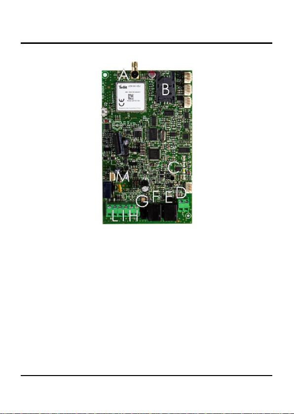
Hardware description
➢Remove the cover.
A ANTENNA cable connector
B SIM CARD housing
C LED indicating device operation status (red), LED indicating data transmission
(yellow), LED indicating power supply status (blue), LED indicating signal
strength (green) and LED indicating line status (white)
D Intercom input (terminal block) for connecting a dedicated telephone for
communication and programming of the connected autodialer
E Intercom input (RJ11 connector) for connecting a dedicated telephone for
communication and programming of the connected autodialer
F Telephone line output (RJ11 connector) for telephone set connection or
autodialer/PABX analogue line connection
G 230 Vac external adapter input
H Telephone line output (terminal block) for telephone set connection or
autodialer/PABX analogue line connection
I 12 or 24 Vdc power supply terminal block
L Relay terminal block
M Backup battery connector
Page 9
INSTALLATION
Inserting the SIM card
Before inserting or replacing the SIM card, always make sure that the
gateway has been disconnected from the mains and battery and that no
electrostatic discharge is present in order to avoid damaging it.
Take all necessary measures to avoid electrostatic discharge.
➢Slide the SIM card housing cover downward until it unblocks and
lift it.
➢Carefully slide the SIM card into its housing cover.
➢Lower the SIM card housing cover and slide it upwards until it
locks.
WARNING
The SIM card PIN must be DISABLED. If the PIN is
enabled, it must be disabled through a mobile phone.
Connecting the antenna
➢Screw the antenna cable in to the connector on the top of the
module.
WARNING
NEVER connect the gateway without having previously
connected the antenna. The gateway may get damaged.
WARNING
Do not install the product near other electric or
electronic devices that were not especially designed to
be used with it. They could be subjected to RF
interference from the module.
Page 10
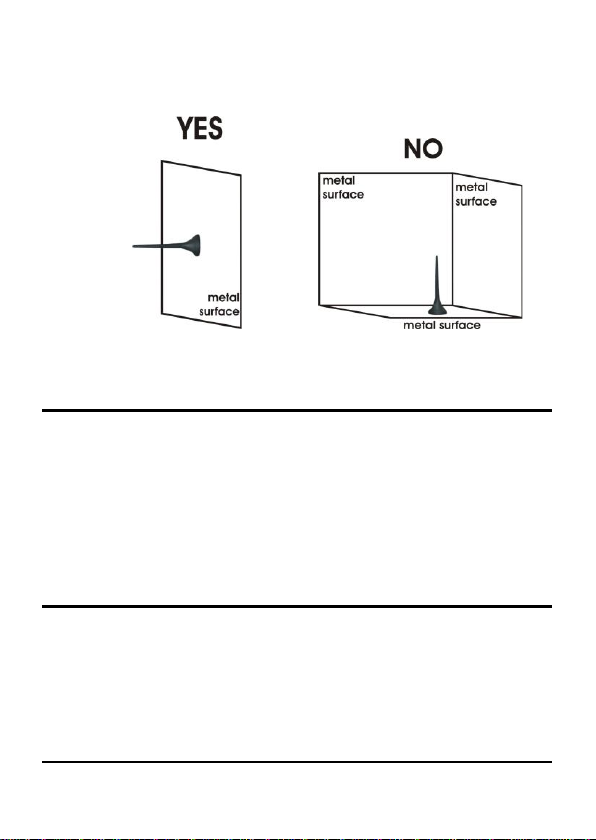
➢Position the antenna with magnetic base so that any metal
surfaces do not block the signal.
Connection to the telephone line
➢Connect the gateway to a standard telephone or to the PSTN input
terminals of a PABX or autodialer via the LINE RJ-11 connector (F
in the picture at page 8).
or
➢Connect the gateway to a standard telephone or to the PSTN input
terminals of a PABX or autodialer using the LINE terminal (H in the
picture at page 8).
Intercom connection
➢Connect the gateway to a standard telephone via the INTERCOM
connector (E in the picture at page 8) in order to communicate or
programme the connected autodialer.
or
➢Connect the gateway to a standard telephone using the INTERCOM
terminal (D in the picture at page 8) in order to communicate or
programme the connected autodialer.
Andere Handbücher für 4G.VoLTE
2
Inhaltsverzeichnis


