Everstar MPK-10CR Bedienungsanleitung

PORTABLE AIR CONDITIONER
USE & CARE MANUAL
Read and follow all safety rules and operating instructions before
first use of this product.

Table Of Contents
Page
1
Introduction.......................................................................................2
Electrical Specifications....................................................................3
Energy-Saving Tips...........................................................................4
Window Installation...........................................................................4
Operating Instructions.......................................................................5
Care and Maintenance....................................................................14
Remote Controller Features............................................................15
Air Conditioner Warranty.................................................................18
Unit Parts Identification
Operation Panel
Vertical Louver
Blades
Caster
Carrying Handle
(both side)
Water Tank
Adjustable Vertical
Louver

Do not leave this unit unattended in a space
where people or animals who cannot react to a
failed unit are located. A failed unit can cause
extreme overheating or death in such an
enclosed, unattended space.
CAUTION
!!
2
Introduction
This Owners Manual will provide you with valuable information necessary for the proper care and main-
tenance of your new appliance. If properly maintained, you appliance will give you many years of trouble
free operation. Please take a few moments and read the instructions thoroughly and familiarize yourself
with all of the operational aspects of this appliance.
Your Portable Air-Conditioner is a multi-functional room air-exchanging, air-processing appliance, designed
to offer you the functions of: Cooling, Dehumidifying and Independent Fan. This unit can be conveniently
moved from room to room within your home and setup in just minutes.
It is recommended that the air processing appliance is in an upright position at all times for proper operation
and efficiency. If the air processing appliance has been placed in a horizontal ( unit placed on side) position,
the unit must be placed in an upright position for a minimum of two hours prior to operation.
For easy reference, may we suggest you attach a copy of your sales slip/receipt to this page, along with
the following information which is located on the manufacturers nameplate located on the rear panel of the
unit.
Model Number:
Serial Number:
Date of Purchase:
Dealer"s Name and Address:
This information will be required if your unit requires servicing and/or for general inquiries.
Keep these instructions for future reference.
This symbol denotes a caution or warning.
!

1. All wiring must comply with local and national
electrical codes and be installed by a qualified
electrician. If you have any questions regarding
the following instructions, contact a qualified
electrician.
2. Check available power supply and resolve any
wiring problems BEFORE installation and
operation of this unit.
3. This unit draws 9.6 amps (nameplate rated)
under Cooling mode and may be used in
any properly wired, general purpose 15 amp
household grounded receptacle.
4. For your safety and protection, this unit is
grounded through the power cord plug when
plugged into a matching wall outlet. If you are
not sure whether the wall outlets in your home
are properly grounded, please consult a
qualified electrician. DO NOT USE PLUG
ADAPTERS OR EXTENSION CORDS.
5. The manufacturers nameplate is located on the
rear panel of the unit and contains electrical
and other technical data specific to this unit.
6. To avoid the possibility of personal injury, always
disconnect the power supply to the unit, before
installing and/or servicing.
Electrical Specifications
Unit Specifications:
Cooling Capacity
Heating Capacity
Dehumidifying Capacity
Noise Level
Power Source
Refrigerant
Water Tank Capacity
Unit Weight
Unit Dimensions(inches)W D H
Unit Dimensions(cm)W D H
Fan speeds
Control Panel(llluninated)
Time of Day Clock
Auto - Timer
Power Consumption:
Cooling
Heating
Fan
NOTE: Product features or Specifications as described or illustrated are subject to change without notice.
10000 Btu/h
Not Applicable
76 Pints (36L/24Hrs)
Less than 54 dB(A)
115V / 60Hz
R22
3.5L(7.4Pints)
33kg(72.7 lb.)
12.8" 18.1" 33.1"
32.5 46 84
3
Soft Touch Controls
No
Yes
1100Watts(9.6 Amps)
Not Applicable
90W(0.8Amps)
Table 1
Suggested Individual Branch Circuit
Receptacle and Fuse Types
Nameplate Amps
7.4 to 12.0
Rated Volts 115
AWG-American Wire Gage
o
Based on copper wire at 60 C temperature rating.
AWG Wire Size
14
Table 2
Wall Outlet
Fuse Size
Time Delay Fuse Plug Type
(or circuit breaker)
Amps 15
3
MODEL MPK-10CR

This appliance is designed to be highly
efficient in energy savings. Follow these
recommendations for greater efficiency.
1) Select a thermostat setting that suits your
comfort needs and leave at that chosen
setting.
2) The air filter is very efficient in removing
airborne particles. Keep the air filter clean at
all times.
3) Use drapes, curtains or shades to keep
direct sunlight from penetrating and heating
room, but do not allow drapes or curtains to
obstruct the air flow around the unit.
4) Start your air conditioner before the outdoor air
becomes hot and uncomfortable. This avoids an
initial period of discomfort while the unit is cooling
off the room. Use of the automatic start / stop
programmable TIMER feature can be a major
asset in this regard if utilized to the fullest extent.
5) When outdoor temperatures are cool enough,
turn the air conditioner off and use the FAN
MODE on HIGH, MED or LOW. This circulates
indoor air, providing some cooling comfort and
utilizes less electricity.
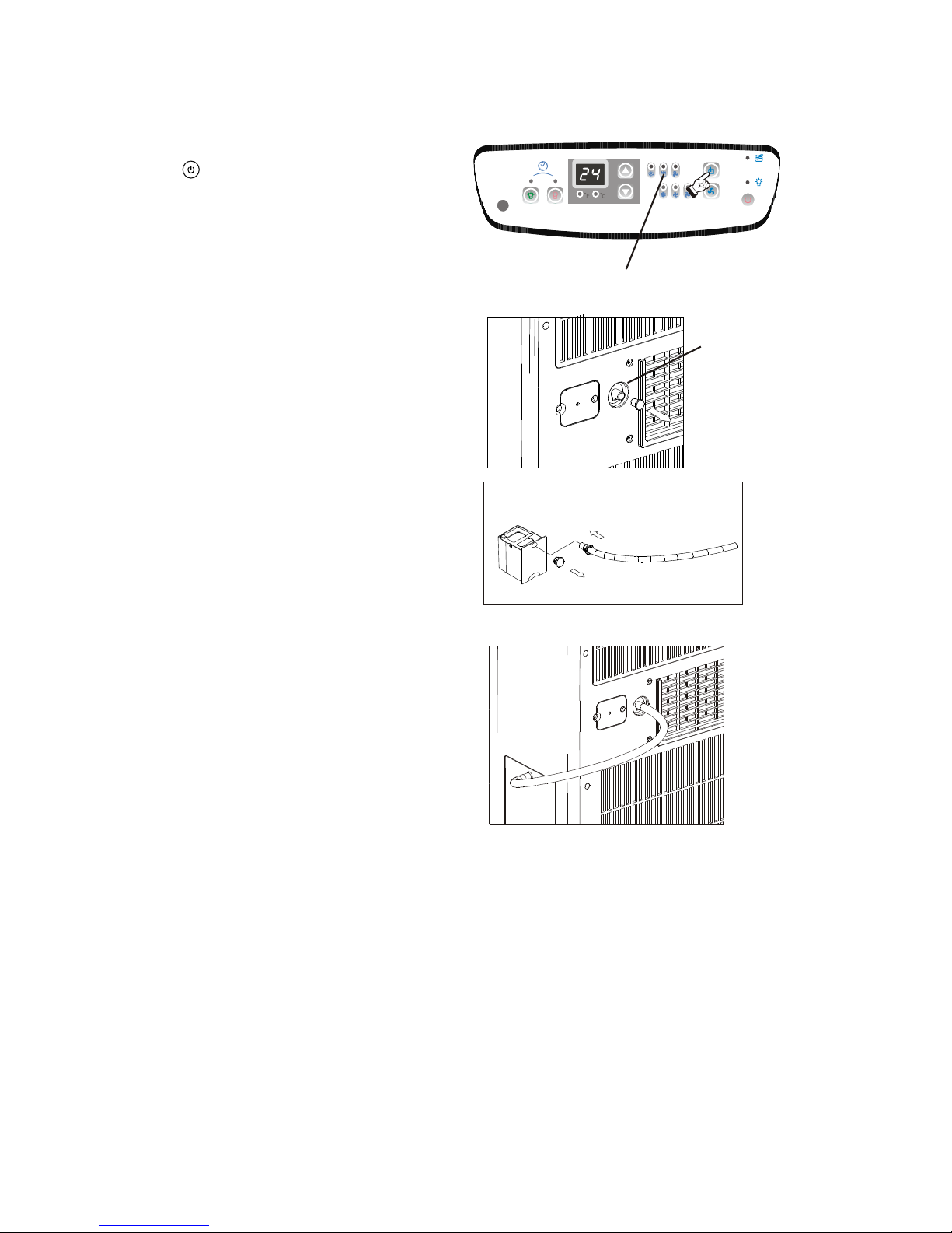
The exhaust/window kit must be installed at all times
when the unit is operating under the COOLING mode.
There should be at least 11.8"(30 cm) clearance
between the unit and any other objects or building
structure. The unit should be installed on a level
surface. The window kit does not have to be installed
during operation of the remaining two modes.
(Dehumidifying/Fan).
Energy-Saving Tips
Window Installation
Installation Accessories Fig.1
Description Qty
Flexible exhaust hose with adapters.........3/pc
stretches from 31" (79cm) up to 89" (226cm)
Window exhaust adapter(flat mouth)...........1pc
Adjustable window/window slider kit....2/pc
17
from 26 / " (67.3cm) up to 47 / "(121.6cm)
28
Drain hose connector..................................1 pc
SPECIAL NOTE: Exterior drain hose extension
(direct drain) is not included with this unit and can
be purchased through any local Hardware Store.
Electric Shock Hazard
To avoid the possibility of personal
injury, disconnect power to the unit
before installing or servicing.
To avoid installation/operation difficulties,
read these instructions thorughly.
4
Fig. 1 InstallationAccessories
Window Exhaust
Adapter
Transition Adapter
UnitConnection
Flexible Exhaust Hose
31 - 89""
CAUTION
!!

Window Kit Installation
Your window kit has been designed to fit most
standard "vertical"and "horizontal" window
applications. However, it may be necessary for
you to improvise/modify some aspects of the
installation procedures for certain types of
windows. Please refer to Fig. 2 & Fig. 2a for
minimum and maximum window openings.
Before Starting This Unit
1) Select a suitable location, making sure you
have easy access to an electrical outlet.
2) Install the Flexible Exhaust Hose and the
Adjustable Window Slider Kit as depicted in
Fig. 3 & Fig. 3a.
3) Plug the unit into a 115V / 60Hz grounded
electrical outlet (Refer to the nameplate).
DO NOT USE AN EXTENSION CORD.
4) Make sure the Water Tank is correctly
positioned inside the cabinet otherwise the
unit will not operate. Fig 4.
5) To turn the unit on, press the POWER key
(On / Off Switch). Fig. 5.
Water Tank Safety Feature
This unit is equipped with a fail-safe switch
mechanism which prevents the unit from
condensing water in the event the water tank is
accidentally displaced, and / or FULL with water.
If this situation occurs, the LED window shows
"P1" and the WATER FULL indicator light will
flash red continuously until the water tank is
correctly positioned and/or emptied.
NOTE: The fan motor will continue to operate
under this condition. This is normal, but no
cooling or dehumidifying will occur until the
tank is emptied and/or correctly installed (It
may take several minutes before the
compressor resumes normal operation).
Operating Instructions
Window Slider Kit
Minimum: 4"(10.1cm )
1
Maximum: 73 / "(186.7cm)
2
Window Slider Kit
Minimum:
7
Maximum: 47 / "(121.6cm)
8
1
26 / " (67.3cm)
2
Horizontal Window
Vertical
Window
Fig. 2
5
Fig. 2a
Fig. 3 Fig. 3a
Fig. 4
Fig. 5

Key Pad Functions Fig.6
Power On/Off.
Selects the appropriate operating mode.
Cool-Dry (Dehumidify)-Fan
MODE Indicator Lights: Illuminates under the
different mode settings. Fig.7.
COOL Mode: Green light
DRY(Dehumidifier)Mode: Green light
FAN Mode: Green light
Green Light : Remains on while compressor is
operating. Green light turns off when desired
temperature is achieved.
Water Full Indicator Light: Flashes red
when the water level of the water tank
exceeds the maximum set level or if the
water tank is not correctly positioned in the
cabinet. Fig. 8.
:Selects High-Medium-Low fan speeds
Fan Options:
Cooling (3 speeds) High-Medium-LOW.
Dry-Dehumidifying (1 speed) High.
Fan (3 speeds) High-Medium-Low.
Fig.6
Fig.7
Fig.8
Green light while cooling
Green light while dehumidifying
Green light while fan only
The LCD window will shows
"P1" and the Water Full
indicator will flash every 0.5
seconds.
Temperature Conversion Chart
OC 10 11 12 13 14 15 16 17 18 19 20 21
OF 48 50 52 54 56 58 60 62 64 66 68 70
OC 22 23 24 25 26 27 28 29 30 31 32 33
OF 72 74 76 78 80 82 84 86 88 90 92 94
6
Used to adjust (forward) temperature
oo
settings (1 C/2 F increments).
Used to adjust (backward) temperature
oo
settings (1 C/2 F increments).
(High) (Medium) (LOW)
TIMER ON: Used to initiate the AUTO ON start
time program, and adjust Auto-Timer settings.
TIMER OFF: Used to initiate the AUTO OFF stop
time program, and adjust Auto-Timer settings.
LED Window: Shows the setting temperature
and Auto-On/Off time. While on DRY and FAN
mode, it shows the room temperature.
Note: This appliance provides a feature that will allow
you the option of setting temperatures in "Celsius"or
"Fahrenheit". To change the temperature display on the
main unit, press the ""key pad & "" key pad
oo
"simultaneously" to alternate between the C& F
o
scale. Celsius scale allows adjustments of 1 C
increments. Fahrenheit scale allows adjustment of
o
2 F increments.

Air Conditioner Operating Instructions
1) Install the Flexible Exhaust Hose Fig.9 and
the Adjustable Window / Slider Kit as
depicted in Fig. 2 & 2a on Page 5.
2) Press the (on/off ) key pad to switch on the
unit.
3) Press the MODE key until the COOL indicator
light comes on( Fig.10). Each depression of
the MODE key will advance to a different
mode setting (Cool-Dry ).
4) Press the appropriate or key to select a
suitable temperature setting. The temperature
selected will be indicated in the LED Display
window.
Temperature settings are adjustable between
oo oo
17 C (62 F) to 30 C (88 F). Fig.11.
The green indicator light will come on indicating
the air-conditioning mode is operational (there
may be a slight delay of 10-30 seconds before
the cycle begins, this is normal).
5) Press the FAN key to select the desired fan
speed setting (High-Med-Low). See Fig.12.
Each depression of the fan key will advance to
a different setting.
6) Condensed water will be accumulated in the
water tank. When the tank is full, the LED
window will show "P1" and the Water Full
indicator light start flashing. At this time the air
cooling process will immediately stop.
However, the fan motor will continue to operate
(this is normal). Carefully remove the water
tank from the cabinet and dispose of the water.
Replace the water tank back to it's original
position (in cabinet) and the air cooling
process will automatically resume. It may take
3-5 minutes for the compressor to re-start.
This is normal.
-Fan
7
Fig. 9
Fig. 10
Cool Indicator
Fig. 11
Fig. 12
Fan speed

TEMP.
8
During cooling and dehumidifying modes, if the
compressor cycle is interrupted (unplugged, power
failure, etc.) And reinstated immediately thereafter (within
3-5 minutes), A "compressor protection circuit"is auto-
matically self-affected. The mode indicator light will flash
"green" for approximately 10 seconds, confirming the
protection circuit is activated. The compressor cannot
operate during a "compressor protection" condition (this is
normal). It may take 3-5 minutes before the "protection
circuit" self-deactivates.
DO NOT ATTEMPT TO START THE UNIT
(COMPRESSOR)DURING THIS PERIOD.
Removal and/or partial displacement of the water
tank will cause the compressor to stop operating
(this is a safety feature). Under this condition the
"water full" light will flash (red) continuously until
the tank is corrected. The compressor cannot
operate during a flashing "red" light condition.
Check the following;
1. Is the water tank full?
Empty and re-install water tank.
2. Has the water tank been accidently displaced?
Re-Position water tank.
The "red" light will stop flashing automatically
When the water tank has been emptied and / or
correctly re-positioned.
CAUTION
ATTENTION
!
!
!
!
Fig. 14
Air Conditioner Operating Instructions
(continuous drain)
7) This unit also has provisions for a continuous
"drain" option (for basement applications having
a floor drain). To connect the continuous drain
option, remove the drain plug from the back of
the unit, then install the drain hose. Please
remember to place the open end of the hose into
a bucket or floor drain failure to comply with
these procedures will result in flooding.
Fig13 &13a.
8) To adjust "air flow" direction , (up / down only)
move the louver wheel with finger to the desired
position.Fig.14.
Cooling stops automatically when the set
temperature is achieved. Cooling resumes when
the room temperature rises above the set
temperature level. The temperature has no effect
on the fan operation. Therefore, the fan will
operate continuously (after the compressor has
cycled off) to maintain optimal temperature control.
Fig.13
Remove the
drain plug
Connect the
drain hose
(included)
Fig.13a

DRY (Dehumidifier) Operating Instructions
1) Press the (on/off) key pad to switch on the
unit.
2) Press the MODE key until the DRY indicator
light comes on (Fig.15). Each depression of the
MODE key will advance to a different mode
setting (Cool-Dry ).
3) The green indicator light will come on indicating
the dehumidifying mode is operational .
IMPORTANT: Under the dehumidifying mode, you
cannot select a fan speed or adjust the temperature.
The fan motor operates at a pre-set High Fan
speed and the LED window displays the ambient
temperature.
4) To drain off the water, remove the drain plug from
the back of the unit and connect the drain hose;
then attach the other end of the drain hose to the
water tank as depicted in Fig.16a. Condensation
starts to flow into the internal tank through the
drain hose. Fig.16b. When the tank is full, the
LED window will show "P1" and the Water Full
indicator light start flashing. At this time the
Dehumidifying process will immediately stop.
However, the fan motor will continue to operate
(this is normal). Carefully remove the water tank
from the cabinet and dispose of the water.
Replace the water tank back to it's original
position (in cabinet) and the dehumidifying
process will automatically resume. It may take
3-5 minutes for the compressor to re-start. This
is normal.
5) This unit also has provisions for a continuous
"drain" option (for basement applications having
a floor drain). To connect the continuous drain
option, remove the drain plug from the back of
the unit, then connect the drain hose. Please
remember to place the open end of the hose into
a bucket or floor drain failure to comply with
these procedures may result in flooding.
Fig13 & 13a on page 8.
-Fan
9
Dry Indicator
Remove the drain
plug from the back.
Remove the drain plug and install the drain hose.
Fig.16
Fig.16a
Fig.16b
6) To adjust "air flow" direction, (up / down only) move
the louver wheel with finger to the desired position.
Fig.14 on page 8.
Fig. 15
Inhaltsverzeichnis
Andere Everstar Klimaanlage Handbücher


