
EXCELSENSE SensorShield-1600 Bedienungsanleitung
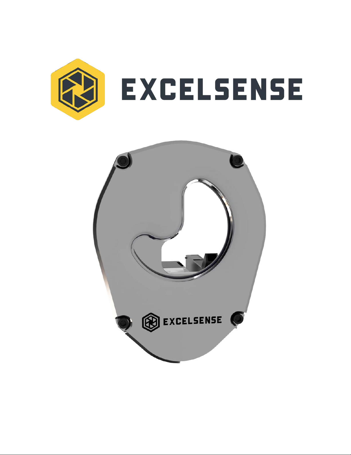
SensorShield-1600™
User Manual, V1.1

Table of Contents
Table of Contents 1
Overview 3
IMPORTANT SAFETY INSTRUCTIONS 4
Warning 4
Caution 5
Specifications 6
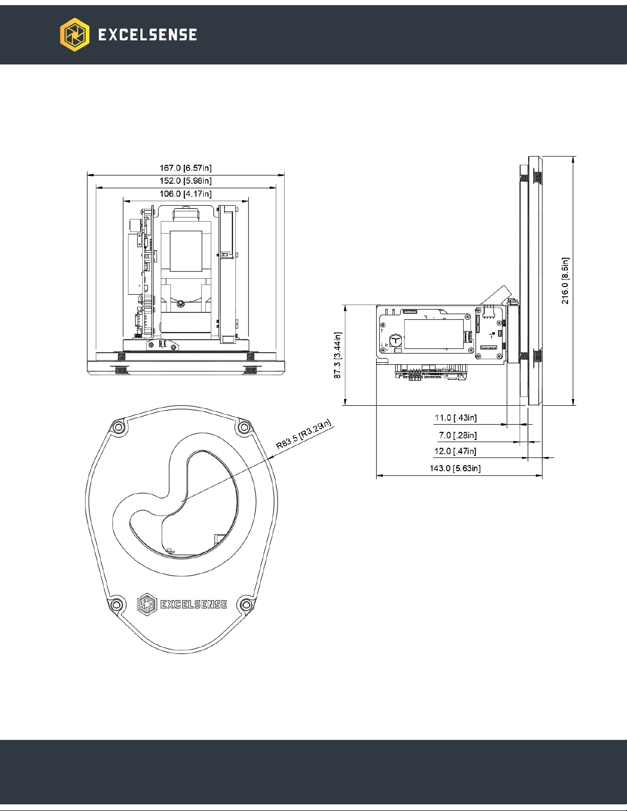
Mechanical Drawings 7
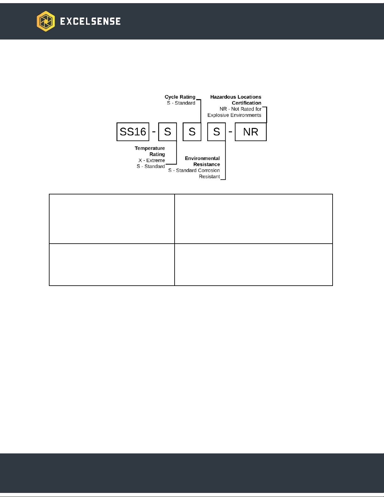
Ordering Options 8
Typical Installations 8
Sensor Mounting 10
Clear Glass Area Dimensions 11
Enclosure Mounting Instructions 12
Accessories 13
Triggering the SensorShield-1600™ 13
Manual Trigger 13
Manual Trigger using External Button 14
Automatic Trigger 15
Thermal Subsystem 15
SensorShield-1600 Thermal Subsystem 16
SensorShield-1600™ Modbus-RTU Interface 16
SensorShield-1600 Modbus Interface 17
Modbus-RTU Settings 19
Modbus Settings 19
Device ID Address 19
Modbus Data Addresses 19
Internal Modbus Server Update Rate 19
RS-232 Settings 19
Supported Function Codes 20
Data Memory Mapping 21
Holding Registers 21
Coils 23
Data Descriptions 24
Holding Register Data 24
DIDR - Device ID Register 24
SREG - System State Register 24
1

EREG - System Error Status Register 25
LCCH - Lifetime Cycle Count High Word Register 28
LCCL - Lifetime Cycle Count Low Word Register 28
LSCR - Lifetime Stall Count Register 29
CTOR - Cycle Timeout Register 29
TCIR - Timed Clean Interval Register 30
LCTR - Last Cycle Time Register 30
CCLR - Cycle Completion Level Register 30
MBTR - Main Board Temperature Register 31
WITR - Window Internal Temperature Register 31
DITR - Device Internal Temperature Register 31
Data Coils 32
PTPC - Power Type Coil 32
PLVC - Power Level Coil 32
RDYC - System Ready Coil 33
THSC - Thermal Heating Status Coil 33
TCEC - Timed Clean Enable Coil 34
LCSC - Last Cycle Status Coil 34
2
Overview
SensorShield-1600™ follows the same self-cleaning principles as the ToughEye-1700™ line of
cameras, providing industry-leading, zero maintenance, self-cleaning operation for
rear-mounted optical sensors and cameras, suitable for any industrial application where a clear
view is critical to the success of the operation.
It incorporates a rugged single-piece design, equipped with our field-proven and innovative
ClearSight™ technology. One can simply integrate this shield into a sensor enclosure by
replicating the indicated panel cutout and the hole pattern.
The SensorShield™ family of optical shields excels at three things: reliability,
zero-maintenance operation and clarity.
ExcelSense can customize SensorShield-1600™ installations for almost any application. Please
3
IMPORTANT SAFETY INSTRUCTIONS
Warning
1. This is an ITE class A device. In a domestic environment this product may cause radio
interference in which case the user may be required to take adequate measures.
2. All electrical connections must be made by qualified personnel in accordance with local
and national electrical codes and regulations. Electrical power is not to be applied to
conductors at any point during this process.
3. Connecting the SensorShield - 1600TM incorrectly poses a risk of injury due to electric
shock to the user, and can damage the device.
4. Damaged or faulty connections may leave electrical conductors bare and/or
short-circuited. Extra care must be taken during installation in order to avoid this
scenario. In such a circumstance, do not attempt to handle conductors before removing
power.
5. The SensorShield-1600™ viewing region is made with hardened glass. The user should
take necessary precautions when handling the system. If excessive, direct force is
induced, the glass may break, causing system failure and potential injury to the user.
6. Operating the SensorShield-1600™ in icy conditions, without the Thermal Subsystem
option in place may lead to damage and void the warranty.
4
Caution
1. Alterations or modifications carried out without appropriate authorization may invalidate
the user’s right to operate the equipment.
2. If powering the device using DC voltage, a Class 2 24VDC 3A power supply is
recommended to ensure stable operation. With its internal protection and regulation,
SensorShield-1600™ can be operated with an unregulated 24VDC power supply. In this
scenario, voltage fluctuation limits will be dependent on setup. Refer to the Electrical
Specifications section on SensorShield-1600™ operational limits.
3. Do not attempt to disassemble SensorShield-1600™ in order to access internal
components. Consult ExcelSense for technical support as required.
4. Never face the SensorShield-1600™ directly towards the sun or any bright or reflective
light, which may cause damage to any internal sensors mounted behind it, such as
cameras.
5. Do not remove the SensorShield-1600™ label containing P/N and S/N information for
warranty service.
6. Never expose SensorShield-1600™ to conditions outside those specified in the
Specifications section. Doing this can cause permanent damage to the device.
7. Damaged SensorShield-1600™ equipment must be replaced through an ExcelSense
representative. Failure to do this may cause incompatibilities and permanent damage to
the system.
8. Always clean the SensorShield-1600™ lens by performing cleaning cycles (see
Triggering the SensorShield-1600™ section for details). Do not clean the glass manually.
SensorShield-1600™ may also be pressure washed as an alternative, when fully
enclosed in an IP69 rated enclosure.
5
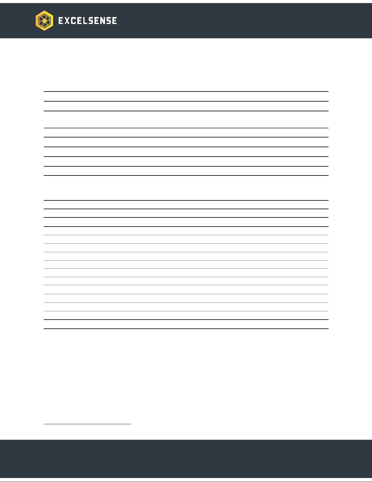
Specifications
GENERAL
Dimensions
167mm width x 216mm height x 143mm depth [6.57” x 8.5” x 5.63”]
Weight
2.0Kg (4.5 lbs), 4.0Kg (8.8 lbs) with Bracket and Sunshield
Power
18~32VDC
Clean Cycle
Automatic: Configurable Timer or Schedule-Based
Manual: Network Command or Electrical Trigger
Temperature Range
-40°C to 60°C (operation and storage)
IP Rating
IP69
Vibration
11g (JIS-D-1601-1995)
Sensor Mounting Holes
M3 x 0.5
External Mounting Holes
M6 x 1.0
ELECTRICAL
Parameter
Min
Typ
Max
Input Voltage, VIN (DC port)
18V
24V
32V
Power Consumption, PIN
5W (Idle)
25W (Heating)
Input Protection (DC port)1
Clamping Voltage, VC
116V
Peak-pulse Power, PPP
6.4kW (28ms pulse duration)
Peak-pulse Current, IPP
35A
Overvoltage Lockout, VOVLO
Engage lockout (rising)
33.3V
Disengage lockout (falling)
33.0V
Undervoltage Lockout, VUVLO
Engage lockout (falling)
17.0V
Disengage lockout (rising)
19.0V
Overcurrent Threshold, IOVC
3A (internal PTC fuse)
Reverse-Polarity, VRVP
[Pulse defined by ISO 7637-2]
Max Cable Length2, LMAX
40m (DC), 100m (PoE+)
Trigger Input, VTRIG
0V / Open
0V (internal
pull-down)
VIN
1Tested as per ISO 16750-2. Designed for complete load isolation during damaging input conditions.
6
Ordering Options
Temperature Rating
X- Extreme: -40oC to 60oC
S- Standard: -10°C (non-freezing) to
60oC
Environmental Resistance
S- Standard Corrosion Resistant
Cycle Rating
S- Standard Cycle Rating 50,000
cycles
Hazardous Locations Certification
NR - Not Rated for Explosive Environments
Typical Installations
Important Note: As per rule 2-024(2) of the Canadian Electrical Code Part I,
SensorShield-1600TM does not require approval in order to be installed. However, it must be
connected to a Class 2 output, as permitted by the Canadian Electrical Code Part I. (See rule
16-222 and relevant appendices).
SensorShield-1600TM is relatively simple to install, requiring only 2 connections with an optional
3rd connection for digital triggering of the self-cleaning functionality:
1. Power the unit with a 30W or larger 24 VDC power supply. Connect 24 VDC and GND to
the appropriate terminals of the blue terminal block on the power board:
8
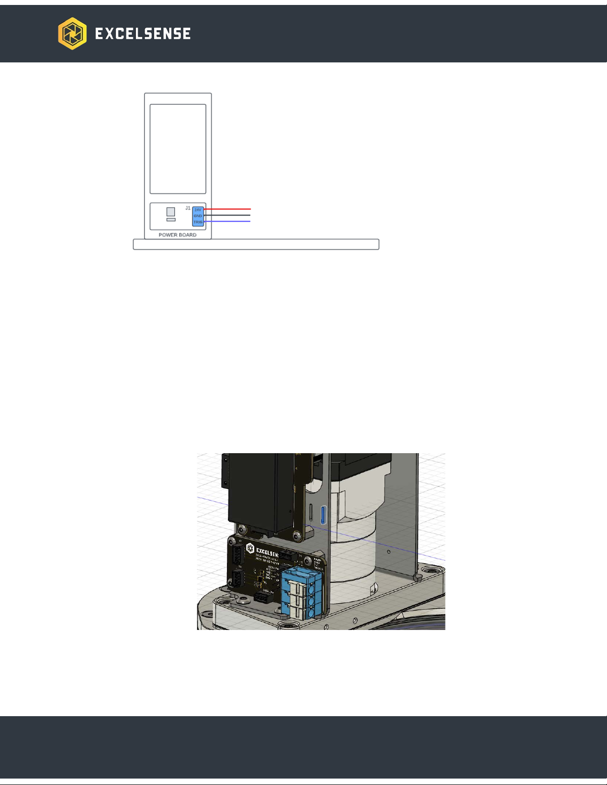
a. The recommended wire gauge for the screwless terminal connections (+V, GND,
TRIG) is 18-22 AWG.
b. The recommended wire finishing method is ferrule application. Wire may be
tinned, where ferrule application is not available.
c. For long cable runs, voltage loss must be taken into account in order to ensure
the voltage at the device does not fall below its minimum voltage (see
Specification table)
2. [Optional] Connect the trigger wire to the trigger terminal of the blue terminal block on
the power board
3. Incoming wires/cables may be fastened to a suitable slot (as highlighted below in blue)
with one or more zip ties:
9
Inhaltsverzeichnis


