ExTe Com 90 Bedienungsanleitung

Art nr: AD00234_Eng REV-A © Copyright Exte fabriks AB.
AD00234 Eng
User Manual
Art nr: AD00234_Eng REV-A © Copyright Exte fabriks AB.
2021-06-16
CC-PILOT
Art nr: AD00234_Se REV-A © Copyright Exte fabriks AB.
Com 90
Com 90

2
Art nr: AD00234_Eng REV-A © Copyright Exte fabriks AB.
Read through the entire manual and fully
understand the content before using the
system!
Bad or faulty mounting and handling can cause
interruptions, damages and personal injury.
Content: Page
Risks and warnings
Components locations and designations
Description of bunks, brake
Mounting of bunks
Mounting of stakes, compl. or only upper stake
Assembly of stakes and lashing arms
Mounting of hydraulic components Truck
Connection of hydraulic pump
Mounting of hydraulic components Trailer
Hydraulic schematic Truck, single stack block
Hydraulic schematic Trailer, double stack block
Schematic overview, Control system
Menu and function guide, CCpilot Control system
Emergency control
Alarms and warnings
Remote control, functions and operation
Loading and unloading
Control system components and connections
Basic circuit diagram
Oil recommendations and pre check
Adjusting pressures and lashing arm speeds
Control system check
Notes, hose length protocol
3
4
5-6
7
8
9-13
14-16
17
18-19
20
21
22
23-29
29
30
31-32
33-34
35-39
40
41
42-43
44-45
46
Can bus system
Manual
Translation from original manual.
Fabriks AB, Gundbergsvägen 6, 827 28 FÄRILA, SWEDEN
Tel: + 46(0)651-175 00
E-mail: [email protected]
www.exte.se
Com 90

3
Art nr: AD00234_Eng REV-A © Copyright Exte fabriks AB.
Risks and warnings.
Always wear a HELMET when maneuvering
and staying close to the Com 90 system!
Always wear PROTECTIVE GLOVES and EYE
PROTECTION when maintaining and repairing
the Com 90 system!
Safety distance min. 5m when operating the
system.
Risk of falling load when maneuvering stakes
and lashing arms.
Hidden tree parts and other debrie
can get in motion!
Even maneuvering an empty vehicle can lead
to risks and surprising situations if you are
too close to the system!
ALWAYS load so that there is a motion
reserve for compression and settling of the
load to avoid the stakes reaching
end of stroke.
More information about emergency stop
functions on page 30.
EMERGENCY STOP
PULL
OR
PUSH
Stop
COM 90
COM 90
COM 90
COM 90
COM 90
COM 90
Min 5m!
!
!
x
!

4
Art nr: AD00234_Eng REV-A © Copyright Exte fabriks AB.
Component locations and designations
1. Hydraulic pump.
2. High pressure filter.
3. Main pressure valve (150 Bar).
4. Direction valve block for single stack (truck).
5. Electrical terminal, I/O unit.
6. Distribution blocks with flow divider.
7. Electrical cable connector, female part.
8. Electrical cable connector, male part on cable.
9. Distribution blocks with flow divider (forward bunk pair).
10. -”- (rear bunk pair).
11. Direction valve block for dubble stack (trailer).
12. Electrical terminals, I/O units.
13. Control panel located in cabin.
14. Radio receiver.
15. Radio transmitter.
16. Quick couplings pressure and return.
17. Quick couplings pressure and return.
18. Termination connector (120 Ohm resistor, used only when driving without trailer if
not auto-termination is used).
2
2
15
9
4
6
3
7
18
17
814
13
16
1
10
11
12
5
Hook LEFT. Ring RIGHT.
COM 90
COM 90
COM 90
COM 90
COM 90
COM 90

5
Art nr: AD00234_Eng REV-A © Copyright Exte fabriks AB.
Description of bunks
1. Bolster
2. Lower stake
3. Upper stake
4. Hook-rib
5. Ring-rib
6. Hydraulic cylinder
7. Sliding sleeve
8. Slide bearing plate
9. Rack
10. Pinion
11. Lashing arm
12. Locking element
13. Mounting plate
14. Securing plate
15. Clamp
16. Fastening plate
17. Screw w. nut
18. Inner frame stop
19. Screw w. nut
20. Brake housing
21. Friction pads
22. Rubber puck
23. Shim
24. Break pin
25. Rib
26. Hook / Ring
27. Locking Pin
The drawing shows Com 90 complete bunk with its different components.
Lashing arm
1
2
3
4
12
5
6
20
21
8
9
10
13
14
22
15
11
16
23
17
18
19
24 25 26
27
7

6
Art nr: AD00234_Eng REV-A © Copyright Exte fabriks AB.
Brake
1
2
3
45
6
7
8
9
9
10
11
Included parts
1. Hydraulic cylinder
2. Brake housing
3. Washer
4. Snap-lock ring
5. Piston seal
6. Piston
7. Support plate
8. Support plate
9. Friction pad
10. Hydraulic line, Brake
11. Seal
Working principle:
Built-in to the upper stake is a brake device that brakes the stake thus enabeling lashing arm
maneuvering instead of stake movement.
When up or down movement is wanted on the stake, the “High speed” function is activated.
The hydraulic pressure to the brakes then significantly reduces to lower the friction against the stake
and enabeling the higher speed but still maintain a secure connection between hook and ring.
!NEVER use the high speed function when moving the
lashing arms!!
ONLY when moving the upper stake UP or DOWN.

7
Art nr: AD00234_Eng REV-A © Copyright Exte fabriks AB.
1
4
7
2
5
6
3
10
8
9
Mounting of bunks
A
Important
In relation to the chassis´ frame
thickness, shim (10) must be used
in appropriate number to achieve
a flat contact surface between the
mounting plate (1) and fastening
plate (7). Gap between frame and
fastening plate, 3-4mm.
See fig. below.
The bunks must always be mounted to the chassis´ frame with a friction attachment (1) Mounting plate.
The friction attachment has a bolted inner stop (2) which must be adjusted to the correct frame width.
It is vital that the inner stop is adjusted correctly.
A slide plate (3) must be placed between the mounting plate and chassis´ frame.
There is a notch in the lower part of the bolster for centering on the chassi (A).
The bunk is fixed by a toothed securing plate (4) against the corresponding teeth in the bolster frame.
Please note that the plate is reversible, which makes it possible to flip the plate for a half
step adjustment.
Slide plunge (5) and spring (6) must be mounted in the fastening plate (7). The bunk is
fixated with the clamp (8) and the rubber puck (9) shall fix the toothed securing plate.
! NOTE! The bolster and stakes are relatively heavy, so
when mounting, you need some type of lifting equipment
(crane or equal) to avoid body injuries.
10
OK
3-4mm
8
Art nr: AD00234_Eng REV-A © Copyright Exte fabriks AB.
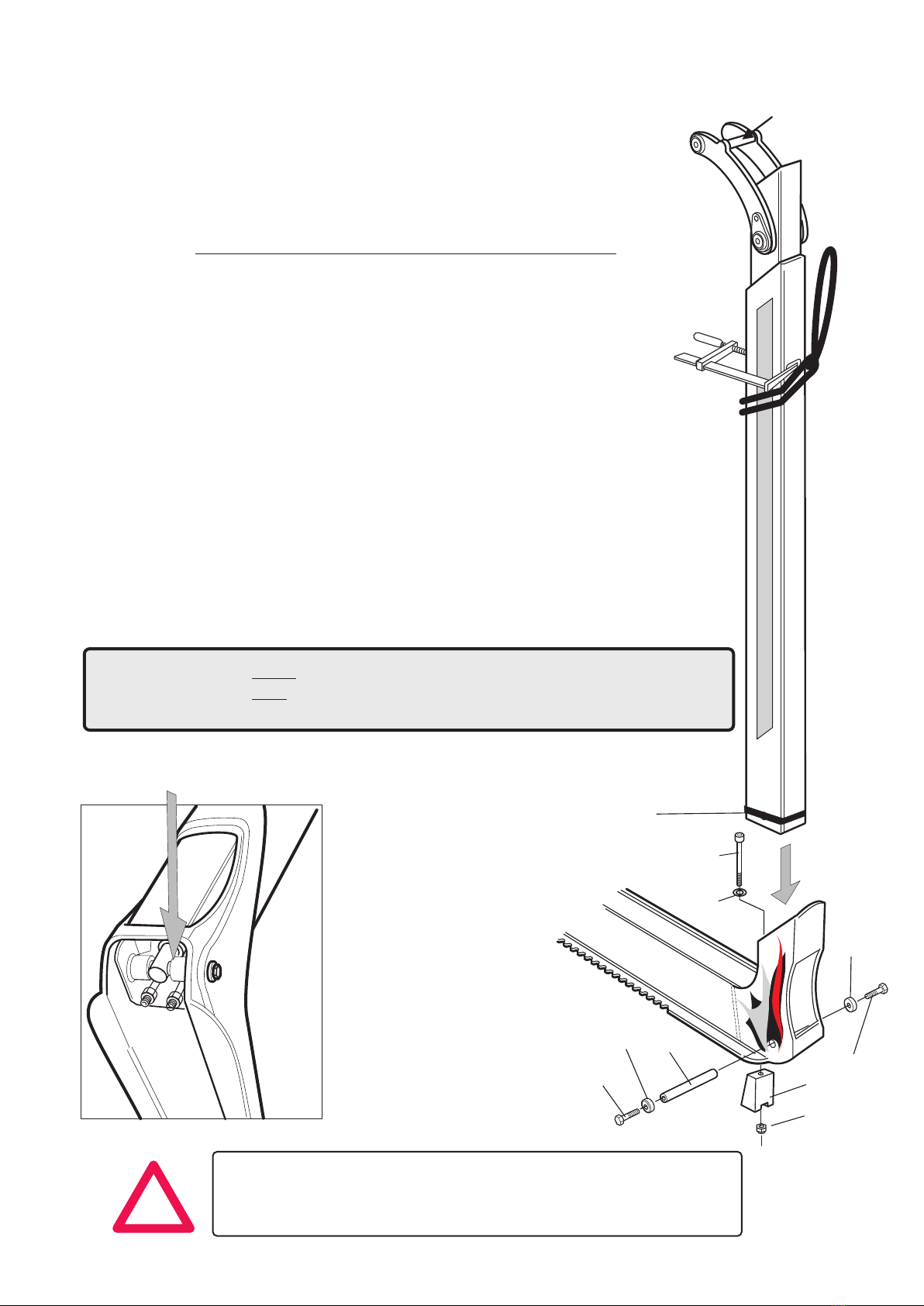
The stakes are delivered from factory pre-mounted with hydraulic
cylinder and brake function.
N.B. Remove tape (1) that holds a transport security device (pin),
that in its turn holds the hydraulic cylinder in place.
Place the stake in the bolster.
Make sure the pin (2) runs through both
the bolster, stake and hydraulic cylinder.
Mounting of complete or only upper stake.
!
When lifting the complete stakes, it’s advantageous to use a strap
(A) that is stopped from sliding by using a clamp as shown in the figure.
When mounting or removing only the upper stake, it can be lifted in
the lashing arm at (B).
When the stake is seated in the bolster, the pin (2) should be mounted by
using it to slide the transport security device away until the pin is all the
way through and in its place. Mount the screws (3) with the washers (4).
Use thread lock.
The locking device (5) shall together with the nut (6) be inserted from below
into the bolster and the screw (7) and washer (8) inserted from the top.
Tighten the screw so the locking device is compressed and therefore
secures the stake in the bolster.
After using the equipment for a while the locking device must be re-tightened
to avoid the stakes vibrating loose.
USE LIFTING DEVISE TO AVOID INJURY!
! NOTE! The bunks and stakes are relatively heavy, so
when mounting, you need some type of lifting equipment
(crane or equal) to avoid body injuries.
1
(A)
(B)
3
4
2
3
4
5
6
7
8
COM 90
Lashing arm with hook shall be mounted on the left side of the vehicle.
Lashing arm with ring shall be mounted on the right side of the vehicle.
See image on pg.4.

9
Art nr: AD00234_Eng REV-A © Copyright Exte fabriks AB.
Assembling the stakes and lashing arms.
At delivery of stakes the lashing arm is normally mounted.
Mounting and removing of lashing arm is described in the following images and
describes the order that is proven and works well.
Hook / Ring Rib
Lashing arm
Rack
Slide bearing plate
Pinion
A
fig. 1
1. Place the upper stake horizontally in a vice.
2. Insert the pinion from the top side of the
stake and direct the axle with mounted keyway
from the side and direct it through the pinion.
Be careful not to damage the keyway or
pinion if the fit is not perfect.
Normally hand power should be enough to push
the shaft through the pinion’s hole.
If necessary a rubber mallet can be used to
lightly tap the shaft.
Friction pads
Light greasing of the shaft is suitable before
mounting. Wood tar can also be used.
Lashing link

10
Art nr: AD00234_Eng REV-A © Copyright Exte fabriks AB.
3. Mount slide bushings from both sides.
There must be a play of min 0.2 mm. between
the stake's bearing guide and the bushing.
The bushing’s hole against the shaft should
have press-fitting and a light tap with a rubber
mallet might be used for mounting.
4. With the rubber mallet, hit the shaft over to
the rear side as in the image and turn it so the
keyway has a 90° angle to the stake pipe.
This is necessary to get a correct mounting of
the hydraulic cylinder to the rack.
Grease the rack with rack grease before
mounting it in the stake.
5. With the slide bearing plate mounted on the
cylinder rack, slide it into the stake pipe’s
bottom end as in figure.
Grease
Assembling the stakes and lashing arms.
Continued.
90°
0,2
Inhaltsverzeichnis
Beliebte Hebesystem Handbücher anderer Marken

morse
morse 82H-124 Bedienungsanleitung

Braun
Braun NL955 Series Bedienungsanleitung

haacon
haacon 1889.10 Bedienungsanleitung

Protekt
Protekt AT 252 Bedienungsanleitung

R. Beck Maschinenbau
R. Beck Maschinenbau HS 600 Bedienungsanleitung

Nova Technology International, LLC
Nova Technology International, LLC NAS Series Bedienungsanleitung

Genie
Genie Z-60/34 Bedienungsanleitung

Screen Technics
Screen Technics INTERFIT Vertical Up Lift Bedienungsanleitung

Mortuary Lift
Mortuary Lift ULTIMATE 1000 Bedienungsanleitung

Custom Equipment
Custom Equipment Hy-Brid 3 Series Programmierhandbuch

Custom Equipment
Custom Equipment Hy-Brid Lifts 2 Series Programmierhandbuch

Hy-Brid Lifts
Hy-Brid Lifts HB-P3.6 Programmierhandbuch


