
FIBARO SMART IMPLANT FGBS-222 Bedienungsanleitung
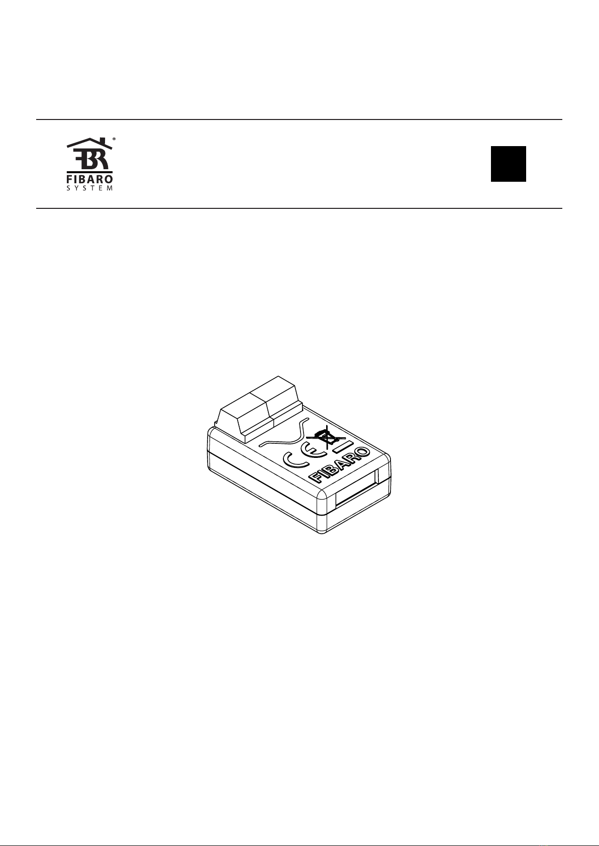
FIBARO SMART IMPLANT
FGBS-222
OPERATING
MANUAL
EN
v1.0


3
Table of contents
1: Important safety information 4
2: Description and features 5
2.1: Description 5
2.2: Main features 5
3: Specications 6
4: Installation 7
4.1: Before installation 7
4.2: Connection with alarm line 9
4.3: Connection with DS18B20 10
4.4: Connection with DHT22 10
4.5: Connection with 2-wire 0-10V sensor 11
4.6: Connection with 3-wire 0-10V sensor 11
4.7: Connection with binary sensor 12
4.8: Connection with button 13
4.9: Connection with gate opener 14
5: Adding to Z-Wave network 15
5.1: Adding manually 15
5.2: Adding using Smart Start 15
6: Removing from Z-Wave network 16
7: Operating the device 17
7.1: Visual indications 17
7.2: Menu 17
7.3: Resetting to factory defaults 18
7.4: Testing operation 18
8: Z-Wave range test 19
9: Activating scenes 20
10: Conguration 21
10.1: Associations 21
10.2: Advanced parameters 21
11: Z-Wave specication 29
12: Regulations 37
4
1: Important safety InformatIon
1: Important safety information
Read this manual before attempting to install the device!
!Failure to observe recommendations included in this manual
may be dangerous or cause a violation of the law. The manu-
facturer, Fibar Group S.A. will not be held responsible for any loss or
damage resulting from not following the instructions of operating
manual.
Do not modify!
!Do not modify this device in any way not included in this man-
ual. It might result in losing warranty privileges otherwise.
Other devices
!The manufacturer, Fibar Group S.A. will not be held responsi-
ble for any damage or loss of warranty privileges for other con-
nected devices if the connection is not compliant with their
manuals.
DANGER!
The device is powered with a secure voltage. Nevertheless, the
user should be careful or should commission the installation to
a qualied person.
DANGER!
To avoid risk of electrical shock, do not operate the device with
wet or moist hands.
This product is intended for indoor use only in dry locations.
!Do not use in damp or wet locations, near a bathtub, sink,
shower, swimming pool, or anywhere else where water or
moisture are present.
Not a toy!
!This product is not a toy. Keep away from children and
animals!

5
2: DescrIptIon anD features
2: Description and features
2.1: Description
FIBARO Smart Implant allows to enhance the functionality of wired
sensors and other devices by adding Z-Wave network communication.
You can connect binary sensors, analog sensors, DS18B20 temper-
ature sensors or DHT22 humidity and temperature sensor to report
their readings to the Z-Wave controller.
It can also control devices by opening/closing output contacts inde-
pendently of the inputs.
2.2: Main features
• Allows for connecting sensors:
»6 DS18B20 sensors,
»1 DHT sensor,
»2 2-wire analog sensor,
»2 3-wire analog sensor,
»2 binary sensors.
• Supports Z-Wave network Security Modes: S0 with AES-128 en-
cryption and S2 Authenticated with PRNG-based encryption.
• Works as a Z-Wave signal repeater.
• Built-in temperature sensor.
• May be used with all devices certied with the Z-Wave Plus cer-
ticate and should be compatible with such devices produced by
other manufacturers.
i
The device is a Security Enabled Z-Wave Plus product
and a Security Enabled Z-Wave Controller must be
used in order to fully utilize the product.
6
3: specIfIcatIons
3: Specications
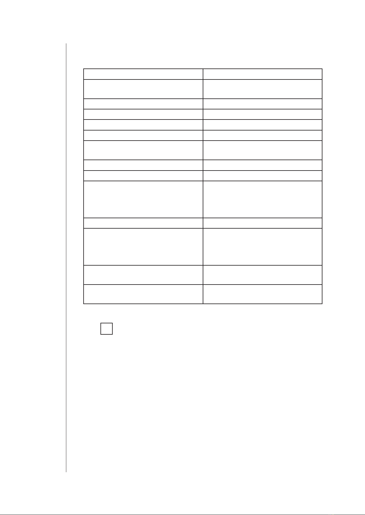
Power supply 9-30V DC ±10%
Inputs 2 0-10V or digital inputs
1 serial 1-wire input
Outputs 2 potential-free outputs
Supported digital sensors 6 DS18B20 or 1 DHT22
Maximum current on outputs 150mA
Maximum voltage on outputs 30V DC / 20V AC ±5%
Built-in temperature sensor
measurement range
-55°C–126°C
(-67°F–259°F)
Operating temperature 0–40°C (32–104°F)
Radio protocol Z-Wave (500 series chip)
Radio frequency 868.4 or 869.8 MHz EU;
908.4, 908.42 or 916.0 MHz US;
921.4 or 919.8 MHz ANZ;
869.0 MHz RU;
Transmit power EIRP max. 7dBm
Range up to 50m (164 ft) outdoors
up to 40m (131 ft) indoors
(depending on terrain
and building structure)
Dimensions
(Length x Width x Height)
29 x 18 x 13 mm
(1.14” x 0.71” x 0.51”)
Compliance with EU directives RoHS 2011/65/EU
RED 2014/53/EU
i
Radio frequency of individual device must be same as
your Z-Wave controller. Check information on the box
or consult your dealer if you are not sure.

7
4: InstallatIon
4: Installation
4.1: Before installation
!Connecting the device in a manner inconsistent with this
manual may cause risk to health, life or material damage.
• Connect only in accordance with one of the diagrams,
• The device is powered with secure voltage; nevertheless, the user
should be extra careful or should commission the installation to a
qualied person,
• Do not connect devices which are not compliant with the
specication,
• Do not connect other sensors than DS18B20 or DHT22 to SP and
SD terminals,
• Do not connect sensors to SP and SD terminals with wires longer
than 3 meters,
• Do not load the device outputs with a current exceeding 150mA,
• Every connected device should be compliant with the relevant
safety standards,
• Unused lines should be left insulated.
Tips for arranging the antenna:
• Locate the antenna as far from metal elements as possible (con-
necting wires, bracket rings, etc.) in order to prevent interferences,
• Metal surfaces in the direct vicinity of the antenna (e.g. ush
mounted metal boxes, metal door frames) may impair signal
reception!
• Do not cut or shorten the antenna - its length is perfectly matched
to the band in which the system operates.
• Make sure no part of the antenna sticks out of the wall switch box.
8
4: InstallatIon
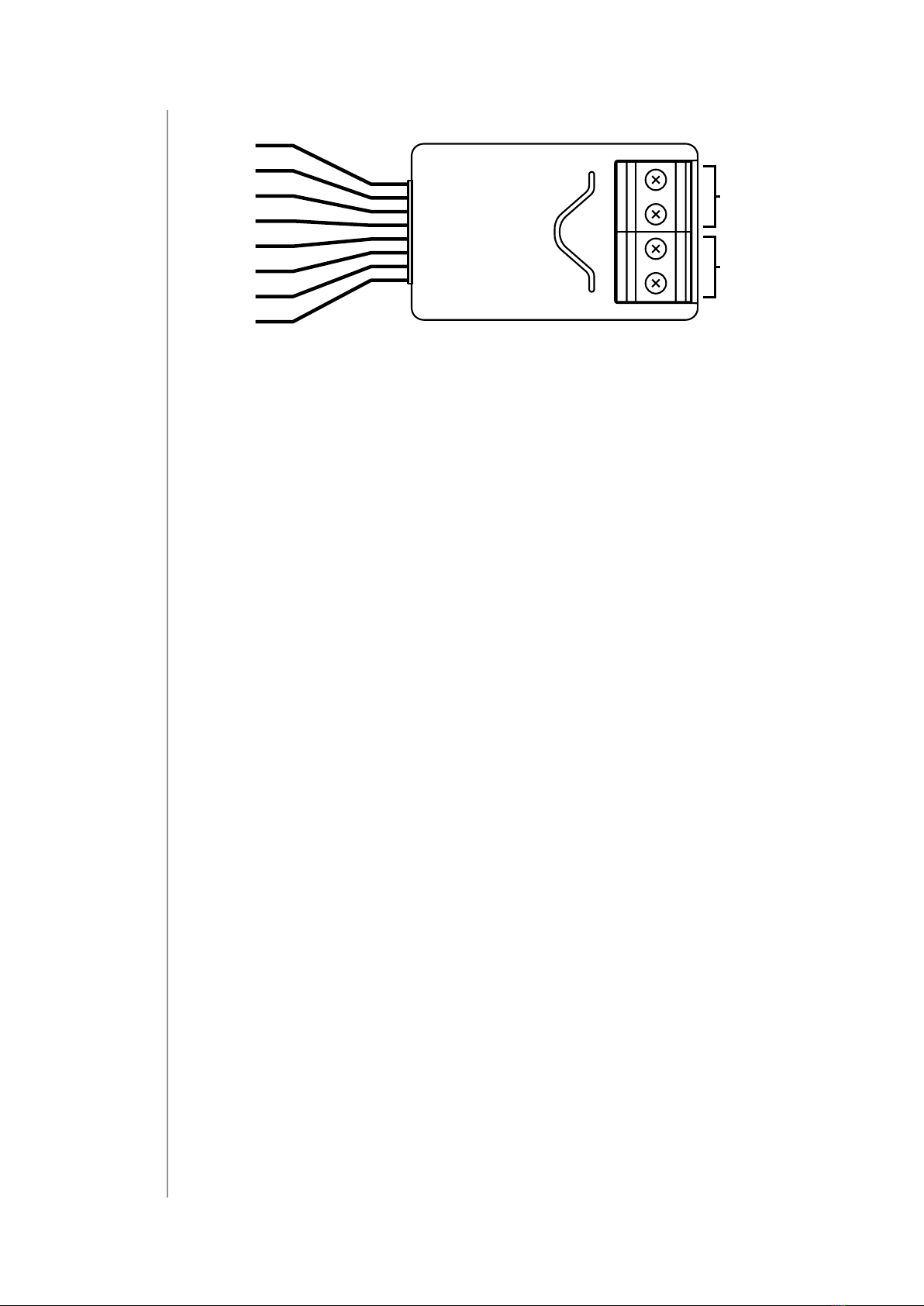
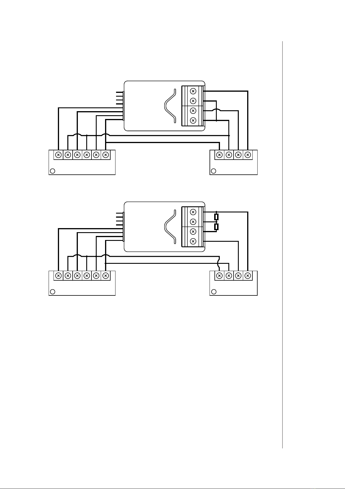
Notes for diagrams:
IN2
IN1
GND
P
ANT
GND
OUT2
OUT1
SD
SP B
ANT (black) – antenna
GND (blue) – ground conductor
SD (white)– signal conductor for DS18B20 or DHT22 sensor
SP (brown) – power supply conductor for DS18B20 or DHT22 sensor
(3.3V)
IN2 (green) – input no. 2
IN1 (yellow) – input no. 1
GND (blue) – ground conductor
P (red) – power supply conductor
OUT1 – output no. 1 assigned to input IN1
OUT2 – output no. 2 assigned to input IN2
B – service button (used to add/remove the device)
9
4: InstallatIon
4.2: Connection with alarm line
1. Turn o the alarm system.
2. Connect with one of the diagrams below:
Z1 Z2AUX COM
IN2
IN1
GND
P
COM 12VTMP TMPNCNC
12
Diagram 1: Example connection with regular alarm line
(1 – alarm sensor, 2 – alarm system hub)
COM 12VTMP TMP COM
R1
R2
Z1COM AUX
IN2
IN1
GND
P
NCNC
12
Diagram 2: Example connection with parametric alarm line
(1 – alarm sensor, 2 – alarm system hub)
3. Verify correctness of connection.
4. Arrange the device and its antenna in the housing.
5. Power the device.
6. Add the device to the Z-Wave network.
7. Change values of parameters:
• Connected to IN1:
»Normally close: change parameter 20 to 0
»Normally open: change parameter 20 to 1
• Connected to IN2:
»Normally close: change parameter 21 to 0
»Normally open: change parameter 21 to 1

10
4: InstallatIon
4.3: Connection with DS18B20
The DS18B20 sensor may easily be installed wherever very precise
temperature measurements are required. If proper protective meas-
ures are undertaken, the sensor may be used in humid environments
or under water, it may be embedded in concrete or placed under the
oor.
You can connect up to 6 DS18B20 sensors in parallel to SP-SD
terminals.
1. Disconnect power.
2. Connect with the diagram below:
VDD
GND
GND
VDD
GND
DQ
DQ
SD
SP
GND
GND 9-30V
P
1
2
Diagram 3: Example connection with 2 DS18B20 sensors
(1,2 – DS18B20 sensor)
3. Verify correctness of connection.
4. Power the device.
5. Add the device to the Z-Wave network.
4.4: Connection with DHT22
The DHT22 sensor may easily be installed wherever humidity and
temperature measurements are required.
You can connect only 1 DHT22 sensor to TP-TD terminals.
1. Disconnect power.
2. Connect with the diagram below:
GND 9-30V
GND
SD
SP
GND
P
GND
DATA
VDD
2
Diagram 4: Example connection with DHT22 sensor
(1 – DHT22 sensor)
Inhaltsverzeichnis
Andere FIBARO Relais Handbücher


