FlexRadio Systems FLEX-6300 Bedienungsanleitung

Page 1 © 2015 FlexRadio Systems, v1.0.2
FLEX-6300 ATU Installation Guide
December 1, 2015
Thank you for purchasing the FLEX-6300 ATU upgrade. The following guide will provide the necessary
step-by-step procedure for installing the ATU upgrade in a FLEX-6300 Signature Series SDR.
Table of Contents
OB TA IN IN G TE CH NI C A L SU P POR T .......................................................................................................... 2
GETTING STARTED..................................................................................................................................... 3
Packaging and ATU Kit Contents........................................................................................................ 3
Additional Required Tools.................................................................................................................. 3
PREPARING FOR THE FLEX-6300 ATU INSTALLATION ....................................................................................... 4
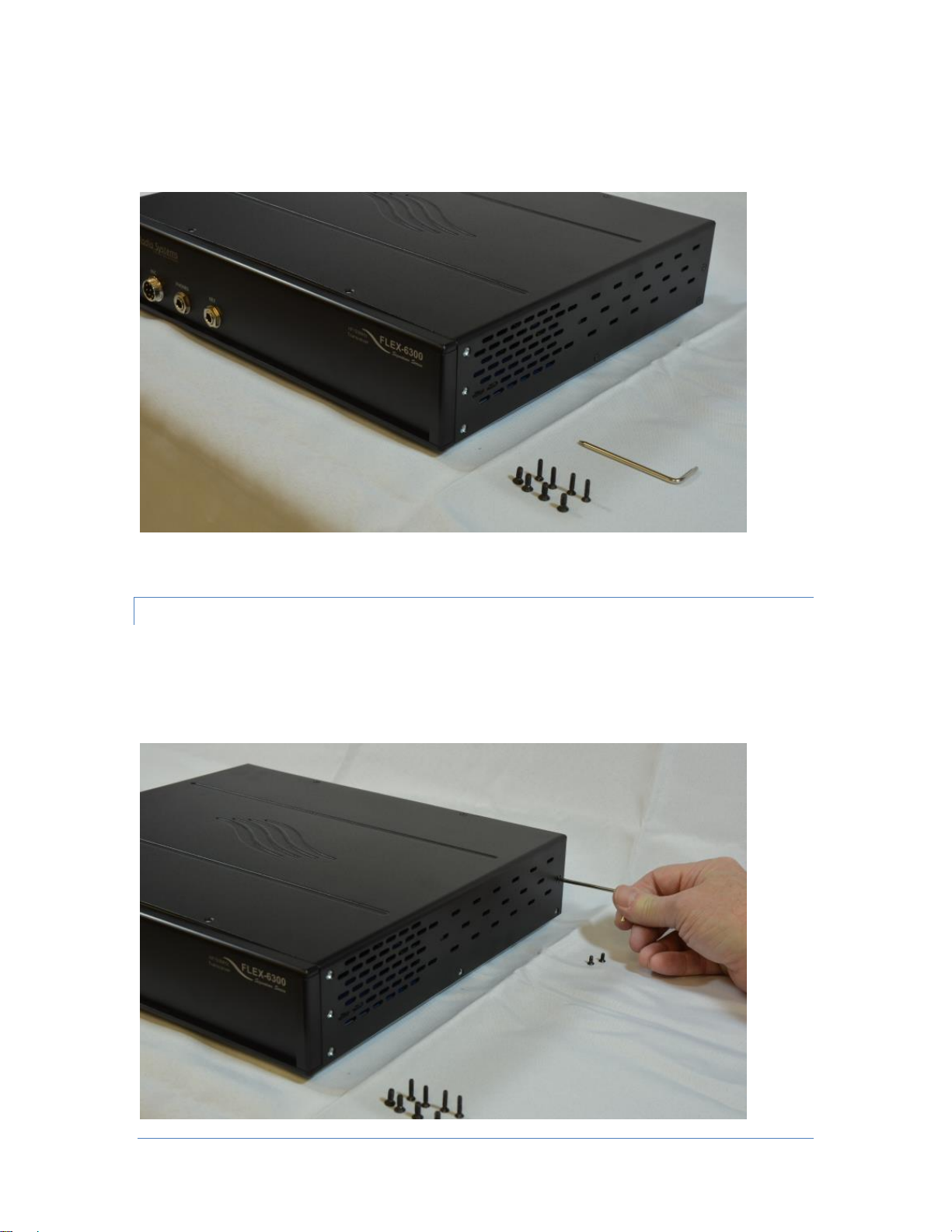
REMOV I NG T HE FLEX-6300 CHAS S I S COV E R ........................................................................................ 4
Removing the Front Side Cover and Top Cover Screws........................................................................ 4
Removing the Middle/Rear Side Cover and Rear Top Cover Screws ................................... 6
Removing the Top Cover.................................................................................................................... 8
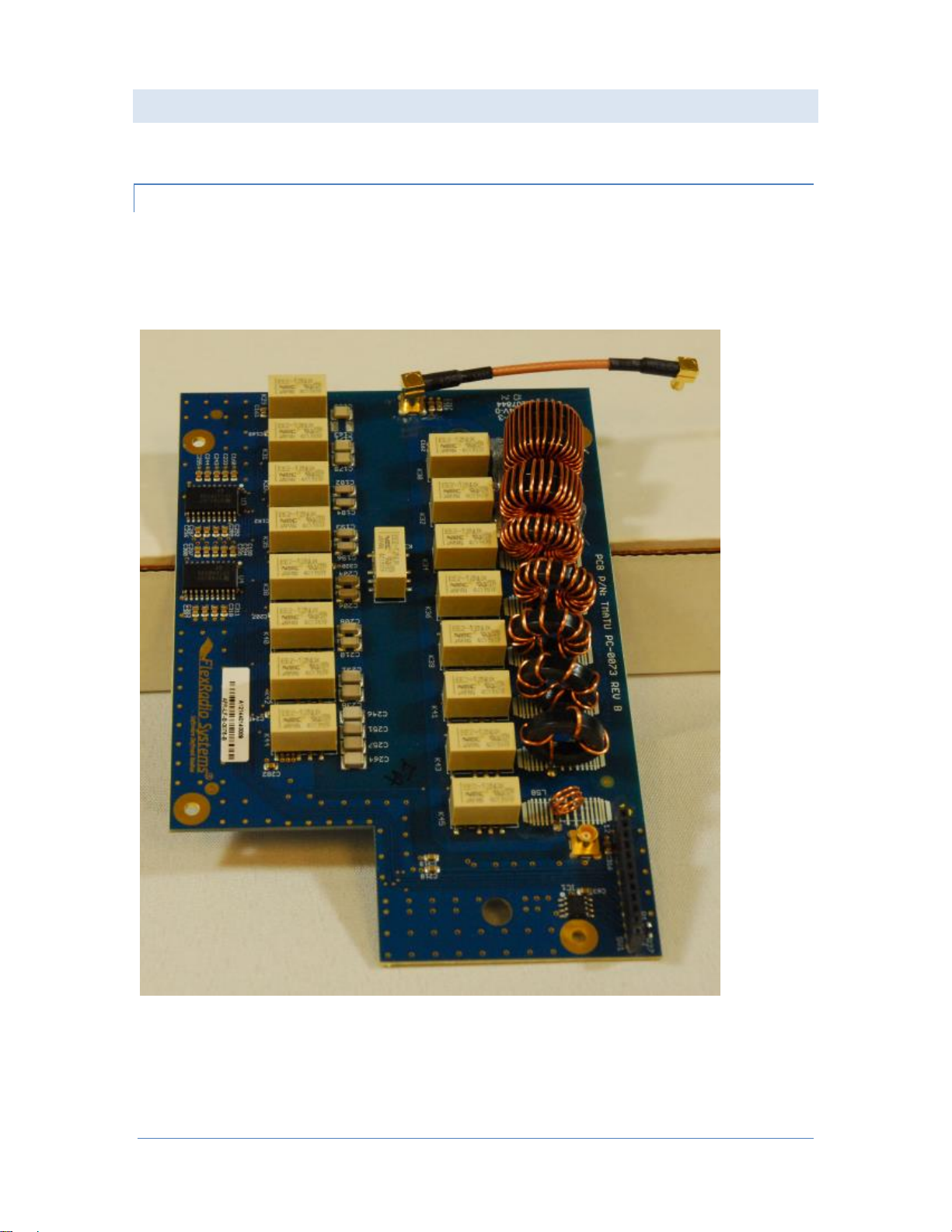
INSTALLING THE FLEX-6300 ATU ASSEMBLY ................................................................................................. 9
Preparing the ATU Assembly ............................................................................................................. 9
Installation of the ATU Assembly into the FLEX-6300........................................................................ 10
Connecting the MCX Cable Assemblies............................................................................................. 13
Installing the ATU12-Pin Jumper...................................................................................................... 15
REI NS TA LL IN G TH E FL EX-6300 CH ASSIS COV ER ................................................................................. 17
Replacing the Chassis Cover ............................................................................................................ 17
Reinstalling the Long Chassis Screws ............................................................................................... 19
Reinstalling the Short Chassis Screws............................................................................................... 21
Applying the ATU Serial Number Label............................................................................................. 22
VERIFYING THE ATU INSTALLATION............................................................................................................. 23

Page 2 © 2015 FlexRadio Systems, v1.0.2
Obtaining Technical Support
If you encounter any issues installing your FLEX-6000 accessory, can request technical support by opening
a HelpDesk support ticket (helpdesk.flexradio.com) or by calling at 512-535-4713 x2. The preferred
method for expedited support is by opening a HelpDesk support ticket.
If you need assistance opening a HelpDesk ticket, please refer to the HelpDesk Assistance Center home
page for step-by-step instructions.
Hours of Operation: Our Technical Support engineers are available Monday –Friday from 9:00am-6:00pm
Central Time. If you contact us after business hours, on a holiday or weekend, please leave a detailed
message and we will return your call during regular business hours in the order it was received.
Another great resource of information is our online user community (community.flexradio.com) where
FlexRadio Staff and other FlexRadio operators post Ideas, Questions, Praises, Problems and solutions. The
Community has powerful search capabilities that allow you to easily locate solutions to questions that
others have previously asked.

Page 3 © 2015 FlexRadio Systems, v1.0.2
Getting Started
Packaging and ATU Kit Contents
Remove the FLEX-6300 ATU Kit contents from the packaging and verify that the following items are
included before proceeding. Refer to the image below.
One (1) ATU assembly, FLEX-6300 ATU board
One (1) Long RG-316 MCX (micro coaxial) cable assembly, 5.2” (13.21 cm)
One (1) Short RG-316 MCX (micro coaxial) cable assembly, 2.7” (6.86 cm)
Four (4) Phillips screws with washers, M3 x 6mm
One (1) 12-pin dual sided jumper
One (1) TORX L wrench, T10 / T8
One (1) ATU serial number label with adhesive backing
Additional Required Tools
In addition to the provided TORX wrench, a #2 Phillips screwdriver is required.

Page 4 © 2015 FlexRadio Systems, v1.0.2
Preparing for the FLEX-6300 ATU Installation
If the FLEX-6300 is powered on, power it off by pressing the Power Button and then remove DC power
from the radio. Disconnect all cables.
Use a flat, well-lighted surface such as a table or work bench to perform the ATU installation.
You may want to use several small containers to store and organize the chassis screws that will be
removed and re-installed as part of the ATU installation.
Make sure to observe basic ESD control procedures to prevent static discharges that may damage
sensitive electronics components inside the radio, such as grounding yourself to reduce static electrical
build up.
Removing the FLEX-6300 Chassis Cover
The FLEX-6300 chassis cover must be removed before installing the ATU assembly.
Removing the Front Side Cover and Top Cover Screws
Remove the 4-40 X ½” Front Side Cover TORX screw using the long portion of the “L” TORX wrench.
Retain the Front Side Cover TORX screw for re-installation. The image below shows the removal of the
right Front Side Cover TORX screw.
Repeat the previous procedure for removing the TORX front side cover screw on the left side of the FLEX-
6300, retaining the screws for re-installation.

Page 5 © 2015 FlexRadio Systems, v1.0.2
After removing the Front Side Cover TORX screws, remove the two (2) 4-40 X ½” Front Top Cover TORX
screws using the long portion of the “L” TORX wrench. Retain the Front Top Cover TORX screws for re-
installation. The image below shows the removal of the left side Front Top Cover TORX screw; the right
side Front Top Cover TORX screw has been previously removed.
After removing the two Front Top Cover TORX screws, remove the two (2) 6-32 x 3/8” flat head Front Side
Cover Phillips screws using a #2 Phillips screwdriver (not provided). Retain the Front Side Cover Phillips
screws for re-installation. The image below shows the removal of the top right Front Side Cover Phillips
screw; the bottom right Front Side Cover Phillips screw has been previously removed.

Page 6 © 2015 FlexRadio Systems, v1.0.2
Repeat the previous procedure for removing the Phillips Front Side Cover screws on the left side of the
FLEX-6300, retaining the screws for re-installation. Keep all removed screws from the previous de-
installation steps separate for re-installation marked as “long” screws. When complete, the FLEX-6300
should look like the image shown below.
Removing the Middle/Rear Side Cover and Rear Top Cover Screws
Remove all three (3) 4-40 X ¼”Middle and Rear Side Cover TORX screws located on the right side of the
FLEX-6300 using the long portion of the “L” TORX wrench. Repeat this procedure for removing the TORX
Middle and Rear Side Cover screw on the left side of the FLEX-6300, retaining all six (6) screws for re-
installation. The image below shows the removal of the right Middle and Rear Side Cover TORX screws.

Page 7 © 2015 FlexRadio Systems, v1.0.2
After removing the Middle and Rear Side Cover TORX screws, remove the two (2) 4-40 X ¼” Rear Top
Cover TORX screws using the long portion of the “L” TORX wrench. Retain the Rear Top Cover TORX
screws for re-installation. (Image not provided).
Keep all removed screws from the previous de-installation steps separate for re-installation. These screws
are shorter than the previous set of screws removed from the FLEX-6300. When complete, the right side
of FLEX-6300 should look like the image shown below with the two sets of screws grouped separately.
NOTE: All top cover screws are removed too.

Page 8 © 2015 FlexRadio Systems, v1.0.2
Removing the Top Cover
With both hands, grasp both sides of the top cover and gently lift upwards to remove the top cover as
shown below. Do not rock the rock the cover from side to side as that may bend the side covers.

Page 9 © 2015 FlexRadio Systems, v1.0.2
Installing the FLEX-6300 ATU Assembly
Once the top cover has been removed, the ATU assembly can be installed.
Preparing the ATU Assembly
Locate the short (2.7” / 6.86 cm) RG-316 MCX cable assembly. Carefully insert one end of the mini RG-
316 Coax cable assembly into the gold MCX “snap on” connector labeled X2 on the ATU board by pressing
down gently until it is completely seated. The X2 connector is located on the edge of the ATU board,
opposite of the notched end as shown below.

Page 10 © 2015 FlexRadio Systems, v1.0.2
Installation of the ATU Assembly into the FLEX-6300
Carefully place the FLEX-6300 ATU assembly in the radio adjacent to the Filter board, aligning up the
copper ringed screw “thru” holes on the ATU board with the female mounting holes (threaded spacers)
on the metal Filter board RF shield. Note that the hole on the center right hand side of the ATU assembly
that does not have a copper ring should have the existing Phillips head screw centered in it when the ATU
assembly is properly seated. Refer to the image below of the ATU assembly being seated in the FLEX-
6300.
Once the ATU assembly is properly seated, very loosely install one (1) M3 x 6mm Phillips head screw using
a #2 Phillips screwdriver in the bottom right hand corner mounting hole (facing the front of the FLEX-
6300) as shown below. Do not tighten the screw at this time.
Inhaltsverzeichnis
Andere FlexRadio Systems Steuereinheit Handbücher
Beliebte Steuereinheit Handbücher anderer Marken

Festo
Festo Compact Performance CP-FB6-E Stücklistenhandbuch

Elo TouchSystems
Elo TouchSystems DMS-SA19P-EXTME Bedienungsanleitung

JS Automation
JS Automation MPC3034A Bedienungsanleitung

JAUDT
JAUDT SW GII 6406 Series Kurzanleitung

Spektrum
Spektrum Air Module System Bedienungsanleitung

BOC Edwards
BOC Edwards Q Series Bedienungsanleitung


