FLOWROX PV 80 Handbuch

PVPVE-190911-EN
Installation, operation, and maintenance
instructions for Flowrox valves
Open Valve (PV) & Enclosed Valve (PVE)
NOTE
These instructions must be read carefully and understood
prior to the installation, use, and servicing of this
product.
FLOWROX OY
P.O. Box 338
FI-53101 Lappeenranta, Finland
Tel. +358 (0)201 113 311, fax +358 (0)201 113 300
Web: www.flowrox.com

TABLE OF CONTENTS
1GENERAL................................................................................. 1
1.1 General safety instructions for PV & PVE valves ................................................1
2INTRODUCTION TO DEVICE........................................................... 2
2.1 Intended use............................................................................................2
2.2 Construction of device................................................................................2
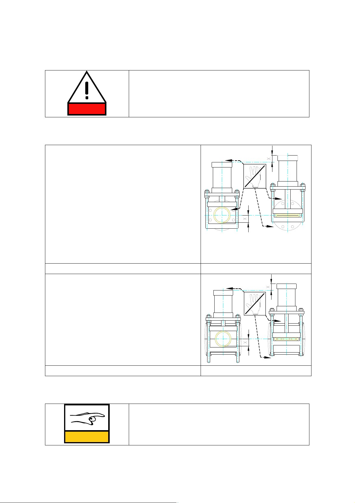
2.2.1 Open body valve PV.................................................................................3
2.2.2 Enclosed body valve PVE ...........................................................................3
2.3 Valve function..........................................................................................4
3TRANSPORTATION, STORAGE AND LIFTING....................................... 5
3.1 Receiving ................................................................................................5
3.2 Storing....................................................................................................5
3.3 Lifting ....................................................................................................5
4INSTALLATION .......................................................................... 6
4.1 Open body model (PV)................................................................................6
4.2 Enclosed body model (PVE)..........................................................................7
4.3 Both models (PV and PVE) ...........................................................................7
5OPERATION.............................................................................. 8
5.1 First use .................................................................................................8
5.2 During operation.......................................................................................8
6MAINTENANCE .......................................................................... 9
6.1 Schedule.................................................................................................9
6.2 Changing the valve sleeve ...........................................................................9
6.2.1 Changing the valve sleeve in open model valve (PV)..........................................9
6.2.2 Changing valve sleeve with enclosed model valve PVE...................................... 10
6.3 Adjusting the valve..................................................................................11
6.4 Troubleshooting......................................................................................13
7TECHNICAL DATA .....................................................................14
7.1 Model and spare part codes .......................................................................14
7.1.1 Valve model selection ............................................................................ 14
7.1.2 Sleeve model selection........................................................................... 15
7.1.3 Sleeve materials for Flowrox valves............................................................ 15
8APPENDIXES............................................................................18
8.1 APPENDIX A: PV- Open Body Assembled ........................................................18
8.2 APPENDIX B: PVE-Enclosed Body Assembled ...................................................19

1
1GENERAL
1.1 General safety instructions for PV & PVE valves
In this manual, the following symbols are used to highlight the parts requiring particular
attention:
SYMBOL DESCRIPTION
DANGER
Risk to personal safety:
Neglecting the safety measures can cause serious
personal injury or death.
Electrical safety:
Neglecting the safety measures can cause serious
personal injury or death.
WARNING
Machinery or environmental risk:
Incorrect maintenance or operation of the product
can harm the environment or the product.
NOTE
Read the operation and maintenance instructions:
Read and understand the operation and
maintenance instructions before using the product.

2
2INTRODUCTION TO DEVICE
2.1 Intended use
Open type PV.
The open body is available in diameters starting from 80mm.
The open body construction is designed for applications with:
•Low pressures
•Low temperatures
•Non-hazardous media
The open body construction is light and simple, which makes it easy to access for service.
The open body also tolerates misalignment and vibration.
Enclosed type PVE.
The valve sleeve is covered by the body housing and thus protected from the
environmental impacts and sunlight.
•Body construction prevents leakage of flowing media to the environment
•The valve body can be equipped with a gauge indicating pressure changes inside the
body
2.2 Construction of device
Flowrox valves are made of three main components:
•flanged valve sleeve
•valve body, either open PV or enclosed PVE
•actuator and actuator control components, if applicable
The valve sleeve is the only part of the valve which is in contact with the medium flowing
in the pipeline.
All valve bodies are flange ended. The standard flange drillings can be made to meet all
standards (e.g. DIN, ANSI, BS, AS, JIS).
The face to face dimensions of Flowrox valves are according to ANSI/ISA 75.10.02:
•165 mm for valves DN25…DN65
•2 ½ times the nominal diameter for valves DN80 and bigger

3
2.2.1 Open body valve PV
Fig. 1.
In the open body model the body and the actuator are connected
only to one of the end flanges (Fig. 1.). The construction allows a
slight deviation in the pipe angle and the valve can act as a
vibration absorber.
WARNING
Note that in case of a sleeve breakage, the flowing liquid
will leak to the environment.
2.2.2 Enclosed body valve PVE
Fig. 2. plug
The body of the enclosed model prevents leakage of flowing
media to the environment (Fig. 2.). The lower part of the body
has a plug, which can be opened to check for sleeve failure.
WARNING
In case of a sleeve failure, slight leakage will occur
through the bushings.
If you open the plug for checking, be careful as the
medium may flow out.
NOTE
Changing the sleeve at appropriate intervals prevents
leakages.

4
2.3 Valve function
DANGER
When the valve closes the actuator moves. Do not put
tools or parts of your body between the moving valve
parts. Note the injury risks (see drawings 3A and 3B).
Note the dangerous places (see drawings 3A and
3B)!
When the pinch valve closes, two pinch bars,
moved by the actuator, squeeze the sleeve,
closing on the center line. As the valve is fully
closed, the actuator has raised one half of the
valve diameter.
The actuator raises in both models (PV and PVE)
0.5 x valve nominal diameter (measure X).
In the open model the space between the pinch
bars, the space between the upper pinch bar and
fixing plate of the actuator and the space below
the lower pinch bar.
Fig. 3A -
PV open model
In the enclosed model the space between the
valve body and the fixing plate of the actuator
and the ends of the guide bars of lower pinch bar
below the valve body.
Fig. 3B -
PVE enclosed model
Regarding the actuators, follow the instructions of the manufacturer.
NOTE
Note the possible remote control of automatic valves and
turn it off before starting maintenance.

5
3TRANSPORTATION, STORAGE AND LIFTING
3.1 Receiving
Check the condition of the valve package on arrival. If it shows signs of transport
damage, check the operation of the valve carefully. Normally, a visual inspection of the
valve is sufficient. However, if valve has been damaged during transport, contact your
nearest Flowrox sales office immediately.
3.2 Storage
The sleeves must be stored as follows:
•The storing temperature should not exceed +25°C, preferably below +15°C but not
under +5 °C. Keep the storage temperature as constant as possible.
•Store the sleeves in a dry place. Prevent water from condensing on sleeve surfaces.
•Avoid ultraviolet light. Protect the sleeves against straight sunlight. Use warehouse
instead of storing outside.
•Remove all equipment generating ozone from the room where sleeves are stored.
Minimize the store room ventilation.
•Store sleeves so that they are free from tension. Sleeves should be stored in vertical
position on smooth support. Do not store sleeves one on top of another.
•Keep the sleeves off the chemical effect of solutions, semi-solids, impurities and
solvent vapours during storing.
•Try to keep the storing time of sleeves as short as possible. Always use first the
material which has been longest in stock.
3.3 Lifting
When lifting the valve, fasten the ropes to the valve body or around it. Note the center
of gravity and support the valve to avoid it turning around. In some models the center of
gravity is located towards the actuator.

6
4INSTALLATION
4.1 Open body model (PV)
Fig. 4.
The sleeve has not been designed to withstand axial forces.
The pipes must therefore be supported properly so that
neither tension nor compression is caused. Use cross-
tightening for flange bolts. Do not overtighten bolts.
Make sure that no inappropriate items get between the
pinch bars and the sleeve.
If possible, protect the sleeve from direct sunlight. Direct
sunlight and UV light deteriorate certain rubber qualities;
this must also be considered during normal use.
A lengthwise angle deviation of max. 5º in the pipe is allowed (Fig. 5).
Fig. 5. Fig. 6.
Deviation in the center line of the pipe (C), (Fig. 6):
PV 80…100 max. 5 mm
PV 125...250 max.10 mm
PV 300…500 max. 15 mm
PV 550…1000 max. 20 mm

7
4.2 Enclosed body model (PVE)
Make sure that no inappropriate items get between the valve body and the actuator.
4.3 Both models (PV and PVE)
The valve nominal size means the inner diameter of the sleeve. The pipe inner diameter
should match this diameter as closely as possible. Whenever possible, install the actuator
in a vertical position. Valve can be assembled either way in terms of flow direction.
If you have to install the actuator horizontally,
it has to be supported to ensure the operation,
especially if the actuator is heavy. Install a sliding
surface under the actuator (Fig 7).
The support can be fixed on the wall (1), on the
floor (2) or the pipeline (3).
The valve can be installed in either way depending
on the flow direction.
When installing the valve to the pipeline, it has to be
in the open position. Tighten the flange bolts smoothly crosswise
Fig. 7.
WARNING Do not fasten actuator or any part of it to the support.

8
5OPERATION
5.1 First use
Flowrox valves are normally delivered fully assembled and ready to use. Check the
condition of the valve visually.
After installation to the pipeline, check that all connections are leak-proof.
5.2 During operation
During the operation the valve does not normally require any maintenance. The sleeve
change is described in 6.2.
To ensure smooth operation, it is recommended to change the valve sleeve regularly.
Regarding the actuators, follow the instructions of the manufacturer.
NOTE
Note the valve functions, see 2.3.
Dieses Handbuch passt für folgende Modelle
21
Inhaltsverzeichnis
Andere FLOWROX Steuereinheit Handbücher
Beliebte Steuereinheit Handbücher anderer Marken

Festo
Festo Compact Performance CP-FB6-E Stücklistenhandbuch

Elo TouchSystems
Elo TouchSystems DMS-SA19P-EXTME Bedienungsanleitung

JS Automation
JS Automation MPC3034A Bedienungsanleitung

JAUDT
JAUDT SW GII 6406 Series Kurzanleitung

Spektrum
Spektrum Air Module System Bedienungsanleitung

BOC Edwards
BOC Edwards Q Series Bedienungsanleitung


