
Fuji Spray V8 Series Bedienungsanleitung


Contents
Contents
Specications
Safety Precautions
Assembly
Operation
Technique
Parts Diagram
Air Cap Sets
Finish Problems
Troubleshooting
Cleaning
Reassembly
Disassembly for Service or Repairs
Warranty Information
1
2
3 - 4
5
6 - 7
7
8 - 9
10
11
12 - 13
14
15 - 16
17
18
1

V8 Series
SPECIFICATIONS
Max. cfm at psi
MP Max. 12.2 cfm at 35 psi
HVLP Max. 14.7 cfm at 28 psi
Air Consumption
MP 12.2 cfm
HVLP 14.7 cfm
Operating Pressure Range
MP 9 to 35 psi
HVLP 9 to 28 psi
Standard Air Cap Set
MP 1.3mm
HVLP 1.4mm
Air Inlet Size 1/4” BSP and NPS
Air Supply Hose Width 5/16” ID
Fluid Coupler Size (Gravity) 3/8” PF
Gun Weight (Without Cup) 521g
Nozzle Sizes Available (in mm) 1.2; 1.3; 1.4; 1.7; 2.0; 2.2
Spray Gun Materials
Body Forged Aluminum
Air Cap Nickel Plated Brass
Nozzle Stainless Steel
Needle Spring Stainless Steel
Fluid Passages Stainless Steel
Seal Gaskets PTFE (Teon)

3
Please read these instructions before using the equipment
FIRE AND EXPLOSION HAZARD
Equipment must not be used in an area contaminated by volatile
or ammable materials. This could ignite the contaminants
causing a dangerous explosion.
• Do not spray ammable or combustible materials near an open
ame or sources of ignition such as cigarettes, motors, and
electrical equipment.
• Never use 1,1,1-Trichloroethane, Methylene Chloride, other
Halogenated Hydrocarbon solvents or uids containing such
solvents in equipment with aluminum wetted parts. Such use
could result in a serious chemical reaction, with the possibility of
explosion. Consult your uid suppliers to ensure that the uids
being used are compatible with aluminum parts.
• Always keep spray area well-ventilated. Always keep a good
supply of fresh air moving through the area.
• Do not smoke in the spray area.
• Do not operate light switches, engines, or similar spark producing
products in the spray area.
• Always keep area clean and free of paint or solvent containers,
rags, and other ammable materials.
• Fire extinguisher equipment shall be present and working.
TOXIC FLUID OR FUMES HAZARD
Toxic uids or fumes can cause serious injury or death if
splashed in the eyes or on skin, inhaled, or swallowed.
• Read MSDS (Material Safety Data Sheet) to know the specic
hazards of the uids you are using.
• Always wear appropriate gloves and eye protection.
• Always wear a respirator. Read all instructions of the respirator
to ensure that it will provide the necessary protection against
the inhalation of harmful vapors. Also check with the local
jurisdiction.
• Paint, solvents, insecticides and other materials may be harmful if
inhaled.
• Store hazardous uid in approved containers and dispose of it
according to applicable guideline.
• Do not stop or deect uid leaks with your hand or body.

V8 Series
EQUIPMENT MISUSE HAZARD
Misuse of equipment can cause serious injury or death.
• Health and safety, accident prevention, work and environment
protection regulations and policies are mandatory.
• Never aim the Spray Gun at another person or animal. In the
event of injury, seek expert medical attention immediately.
• Do not operate or spray near children. Always keep children away
from equipment at all times.
• Do not overreach or stand on an unstable support. Always keep
eective footing and balance.
• Stay alert and watch what you are doing.
• Do not operate the unit when fatigued or under the inuence of
drugs or alcohol.
• Check the hose, hose connectors and Spray Gun before every
use. Any worn or damaged parts should be replaced immediately.
• Before performing any maintenance to the equipment, de-
energize, depressurize, disconnect and lock out all power
sources.
• Use only genuine Fuji Spray replacement parts. Never modify the
equipment.
STATIC CHARGE HAZZARD
Static electricity may be produced by uid. Make sure any electrically
conductive object being sprayed, spray area, and spray equipment is
properly grounded to prevent static sparking. Improper grounding or
sparks can cause a hazardous condition and result in electric shock,
re, or even explosion and other serious harm.
Prop 65 for California Residents
WARNING: This product may contain chemicals known to
the State of California to cause cancer, birth defects, or other
reproductive harm.
Warning: Sound levels produced by spray guns during use may be
harmful to the ear depending on the set-up. It is recommended that
ear protection is always worn at all times when spraying.
THE EMPLOYER IS RESPONSIBLE TO PROVIDE THIS INFORMATION
TO THE OPERATOR OF THE EQUIPMENT

5
ASSEMBLY
Cup Assembly Installation:
Insert Paint Strainer into the base of the Cup from the outside. Attach
the cup assembly by screwing into the Fluid Coupler of the Spray
Gun. Hand-tightened is enough.
Connecting to Air Supply:
1. Attach pressure regulator with gauge (not included) into the
Spray Gun’s air inlet
2. Attach hose connector nipple (not included) to pressure
regulator with gauge
3. Connect air supply hose
(OPTIONAL) Attach hose connector nipple directly into the Spray
Gun’s air inlet and connect air supply hose.
NOTE: For best spray results, it is recommended using a 5/16” ID
air pressure hose. If hose is over 20ft then a 3/8” diameter would
be ideal. Using a smaller diameter hose will result in a signicant
drop in pressure.
NOTE: Air supply must be clean, moisture free, oil free air and
properly regulated.
Most HVLP and MP (Mid-Pressure or reduced pressure) compressor
Spray Guns will operate between 10 and 20cfm. A 20cfm Spray
Gun will drain the air from a moderate sized 5hp compressor. If an
additional air tool is connected to the circuit and used during this
time, the Spray Gun’s atomizing pressure will vary. This will result
in a lower quality performance and inconsistent outcome. For best
results, a larger compressor is recommended.

V8 Series
OPERATION
To clean out any impurities that may have accumulated during
assembly or shipping of the Spray Gun, we recommend spraying a
small quantity of clean paint thinner through the gun. If you intend
to spray water-based paints and materials, make sure uid passages
and components that may have come in contact with paint thinner
are completely dry.
• Mix material to manufacturer’s requirements, and properly
strain.
• Fill the material cup no more than maximum 3/4 full - Do not
overll.
• As a safety guard and reference point, turn Fluid Control Knob
(#15) clockwise, do not force. This will prevent any accidental
trigger pull as you complete setting up.
• Turn the Fan Pattern Control Knob (#16-6) counter-clockwise, this
will set the Spray Gun to the widest fan pattern.
• Connect air supply to the Spray Gun and rotate the Fluid Control
Knob (#15) counter-clockwise two full turns. This will allow for
some material to ow out of the Nozzle to atomize.
• Point Spray Gun away from you, pull the trigger and gauge the
Spray Gun’s settings. You may need to adjust material ow, air
pressure, or fan pattern settings at this time to achieve desired
settings.
Fluid Control - If the material ow is too heavy, turn the Fluid Control
Knob clockwise, this will reduce material volume ow. To increase
material volume ow for a wet nish, turn the Fluid Control Knob
counter-clockwise.
Pressure Regulator - Air pressure adjustment will signicantly
aect how the material is atomized. If looking too coarse when wet,
increase air supply pressure at the pressure regulator located at base
of the Spray Gun’s handle. If looking too ne, decrease pressure. For
pressure specications of the Spray Gun, see page 2.
7
Pattern Control - To produce a smaller fan pattern, turn the Fan
Pattern Control Knob (#16-6) clockwise. For widest pattern, turn Fan
Pattern Control Knob counter-clockwise.
NOTE: In most cases, a combination of all three adjustments will
provide the desired results.
TECHNIQUE
The Spray Gun should be held perpendicular to the surface at all
times. Hold the gun no more than 8” (20cm) away from the surface to
be sprayed.
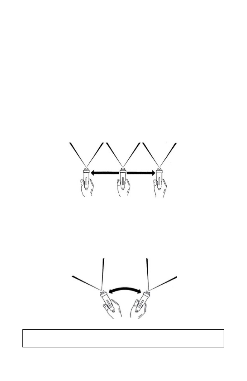
CORRECT METHOD
Begin spraying by pulling the Trigger and move the Spray Gun in
the direction you want to spray. Start your pass from o the edge of
the piece; then continue o the edge of the piece on the other end
before releasing the Trigger. Between each successive pass, overlap
by 50%.
INCORRECT METHOD
CAUTION: Never for any reason point the Spray Gun directly at
the face or head of a person.
V8 Series
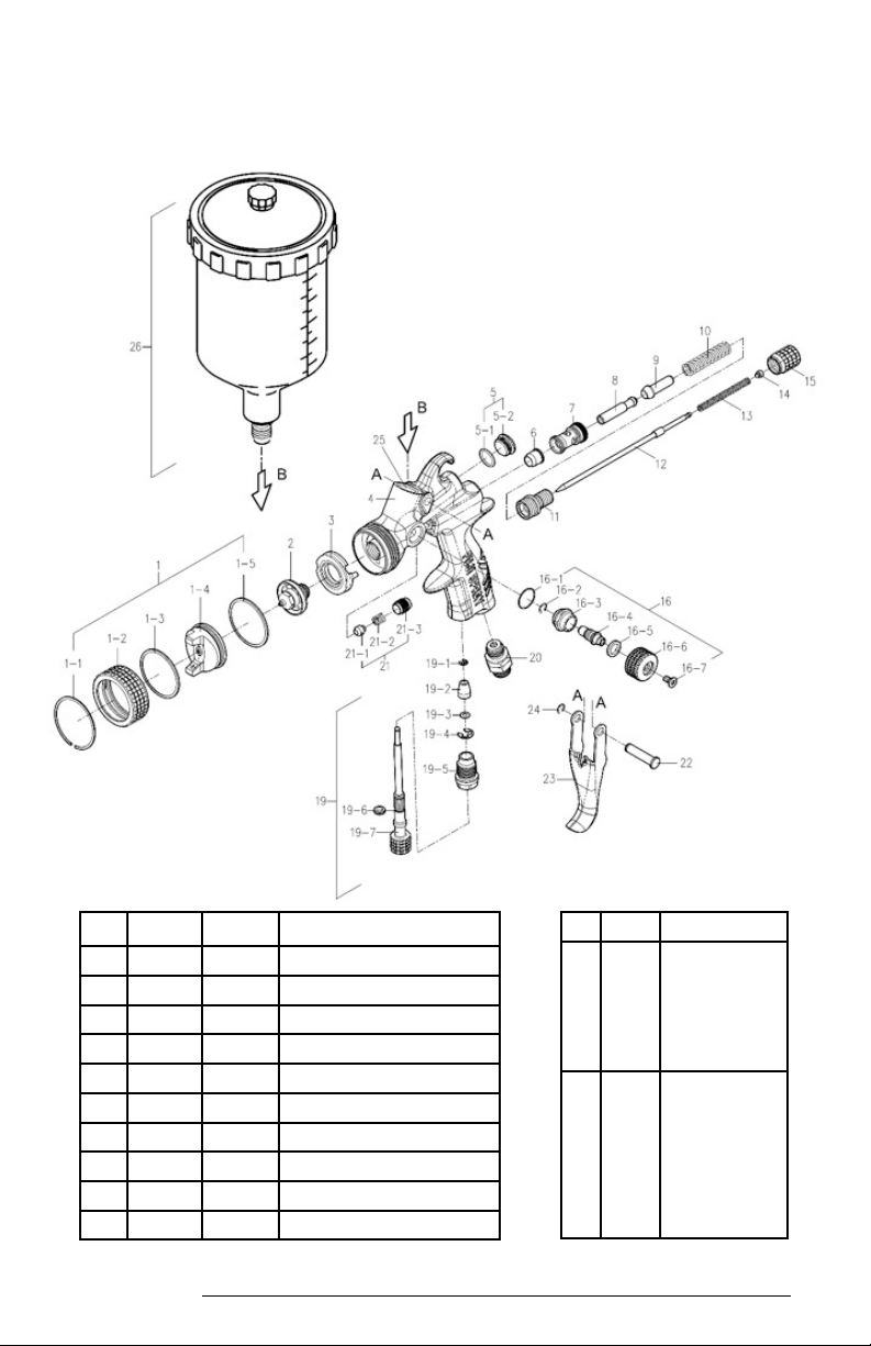
FUJI SPRAY AUTO™ V8 SERIES SPRAY GUN
PART DESCRIPTION
• • 6882 Spray Gun
Rebuild Kit
consists of one
each of these
parts
•Parts not
removable
ITEM PART NAME
1Air Cap with Collar
1-1 Air Cap Retaining Ring
1-2 Collar
1-3 Air Cap O-Ring
1-4 Air Cap
1-5 Collar Seal
2 Fluid Nozzle
• • 3 6803 Air Distributor
4 Gun Body
5 6805 Rear Barrel Plug with Seal
Inhaltsverzeichnis
Andere Fuji Spray Spritzpistole Handbücher


