
Full Spectrum Laser MUSE FIBER GALVO 2 Bedienungsanleitung


Safety Symbols:
Looking for financing or eager to buy, contact Sales:
Need help, visit us at our Help Center or contact Support:
1
Red Icons indicate dangerous situations that could result in serious injury or death.
Indicates a hazardous situation which, if not avoided, will result in death or serious injury.
●This product is rated as a Class 4 machine, however the
presence of an enclosure will make the overall class of
the machine Class 3R.
●If purchased with an enclosure, keep the enclosure closed
when operated to ensure proper ventilation.
●Always wear the provided safety glasses when using your
machine.
●Never stare directly into the laser when the machine is
running. We recommend staying at least 5 ft away from
the machine when in use.
●Avoid using materials made of or containing carbon
components.
●Make sure your exhaust in functioning properly before
each use.
●Do not leave your machine unattended.
●Always keep a fire extinguisher and first aid kit nearby.
●Regularly inspect your fire extinguisher to ensure
functionality.
●Do not attempt to access any electrical areas while the
machine is on.
●Unplug the machine and wait for an hour before
accessing panels.
●Always maintain a clean work area.
●Inspect your machine before each use. Do not use if the
machine or its accessories are damaged in any way.
Safety Warnings:

Safety Stickers:
2
Assembly:
4- m6
screws
M5 hex
key
1. Secure the stage to the
base using the m6 screws.
2. Slid the isolator into position and
screw in place using the m5 screws.
2- m5
screws
M4 hex
key
3. Grab Loom 1 connect the VGA cable to the back of
the scanhead and the Type C cable to the camerahead.
Then grab Loom 2, connect the 3 pin cable to the cable
hanging near the motor and the other into the motor.
Loom 1
Loom 2
4. Place the machine cover over the laser
head assembly and secure it in place.

Laser head
Assembly
Lens
Work Space
Touchscreen
Diagrams:
Wifi Plug
Rotary
Plug
Ethernet
Port
Power Switch
Power Outlet
Connecting to Internet:
Connect Via Router (Recommended):
To establish a reliable link to RE3, it is recommended to connect the Fiber Galvo
to the router. The Fiber Galvo is equipped with an ethernet cable that should be
plugged into the ethernet ports of both devices
Note: Ethernet port looks the same on all devices
Connect to Wi-Fi:
Make sure that the dongle, a device attached to the USB port of your machine, is
present and connected as it enables your machine to connect to the WiFi network.
1. To connect to the WiFi network, select the Network button located on the
top right of the Touchscreen.
2. Then, choose the WiFi option and search for your network. Once you
have located your network, select it and enter your password.
Connecting Directly Using Computer:
This option is only advisable when the other two methods are not possible. The
Fiber Galvo can connect to the computer through Ethernet, but an adapter might
be required for your computer.
3

Touchscreen Interface: Home
The Home screen displays important information such as the device's
IP address, the QR Code for RE3, and controls for the laser head.
Job History
The Job History icon provides easy access to previous projects.
Users can select the file and view its contents, or choose to re-run the
job. Note that an internet connection is not required to use files saved
in this section.
Network ⇨ Wi-Fi
Enables users to connect to a Wi-Fi network.
Mobile Version
A mobile version of the device is accessible by either scanning the
QR Code or entering the device's IP address into the web browser of
a mobile device.
Tools
The Tools icon enables the user to verify and modify the machine
settings, activate rotary attachments, home the laser, and retrieve
relevant information regarding the device.
Machine Indicators:
Wired IP Indicator:
The IP indicator shows if the machine is connected to an ethernet cable.
Connected Not Connected
Wi-Fi Indicator:
The Wi-Fi indicator will indicate if the machine is connected to the Wi-Fi.
Connected Not Connected
Run Job Icon:
Selecting the icon will run the job.
AutoFocus Icon:
The Autofocus icon automatically moves your machines Z-stage to
the height needed to perform an engraving. (Needs QR card to work.)
Camera Capture Icon:
The Camera Capture icon takes images of the workspace.
Preview Job Icon:
Selecting the icon will make the machine outline the area of your
project on your workspace.
Movement Controls:
The movement icon allows the user to adjust the stage's vertical
movement through three adjustable speed settings. The speed
settings can be modified by selecting the prism icon.
4
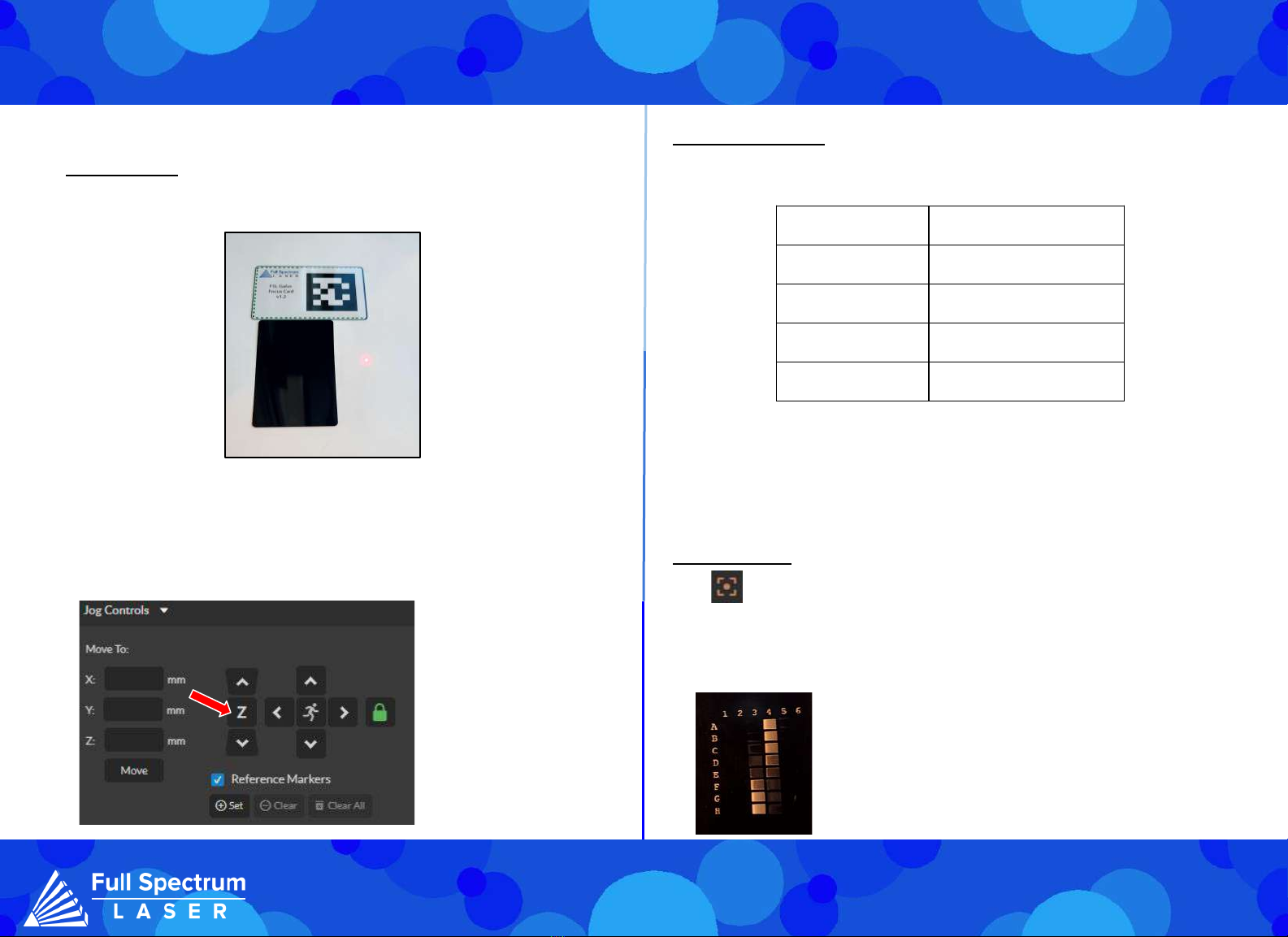
Focusing:
Autofocus
Manual Focus
Retrieve your April tag card first. Ensure that the side of the card labeled "Focus Card V1.2"
is facing upward. Position the card under the camera.
Note: If your machine does not
move when the autofocus
button is hit, then lower the
gantry and try again.
Lens Focal Length Distance from Material
163mm 203mm
254mm 294mm
330mm 370mm
420mm 460mm
Note that the numbers in the chart refer to the distance from the lens to the object, not from
the lens to the workspace. If you switch to a larger object, adjust the stage accordingly.
During manual adjustments, keep an eye on the red diode. When the laser turns on, the red
diode will appear large and fuzzy. As the laser head moves down the stage, the red diode will
become smaller and more focused. Stop adjustment when the diode appears clearest, run
the focusing test to ensure that it falls within the desired range.
Focus Test
Once you’re machine is in position, locate and select the Focus Test Icon.
The Focus Test window will open, ensure that you have selected the appropriate lens size
then select the "Generate Test Pattern" button to produce a grid.
The focal length of the lens determines the amount of distance between it and the
material. Refer to the chart below for the required distance for each of our lenses.
From the grid, choose the two markings that appear most
similar to one another. Enter these markings into the pattern
selection and save the results. For example, in this image we
selected 3F and 4D as they appear to be most similar.
5
There are two methods to autofocus your machine.
● Navigate to the touch screen and selecting the Autofocus icon located on the
Home page.
● Enter RE3 by typing the IP address in the web browser. Then, go to the Jog
Controls, select the Autofocus Icon.

General Maintenance:
By following our maintenance instructions, you can ensure your machine will function at
peak performance for a long time. Please keep in mind that the following maintenance
schedule can vary depending on machine usage.
Before each daily use:
Clean your lens with optical grade wipes.
Cover the lens when not in use.
Make sure all your cables are connected properly.
Make sure your ventilation system is functioning properly.
After weekly use:
Clean your machines workspace with a vacuum to remove small debris.
Check your ventilation system’s filters and clean if needed using a vacuum at low power.
Monthly:
Perform a simple engraving ,such as a square, to make sure the laser diode is aligned
with the laser. Perform the Mark and Preview adjustment if needed.
Check your ventilation system’s filters and replace if needed.
Project Procedure:
Connect to Software
Create or Import Design
Place Material
Focus Lens
Align Material to Engraving Areas
Adjust Object Properties
Run Job
For more information on your machine refer to your user manual. For
information on RE3, refer to the RE3 Guide found in our website.
6

Lens Replacement:
Lens
Lens Collar
Camera
Focusing:
Dual Diode:
A red diode is mounted to the rear of the machine and is positioned to align with the laser diode
when lowered to the lens’ focus point.
Note that when switching lenses, the rear diode will need to be readjusted for the new focal
length. In order to adjust the red diode, focusing your machine to the new lens. Then adjust
the position of the back diode until it aligns with the laser. Once the adjustment is made,
perform a focus test to ensure optimal results.
1. Remove any objects found in the work area. Ensure laser head is in a reachable position to
remove lens.
2. Cover the removed lens with its lens cap.
3. Remove the lens by turning it counter-clockwise.
Avoid touching the glass surface of the lens to prevent scratches. The lens collar may come
loose with the lens,if that occurs remove it with the lens and then reinstall.
4. Install the new lens into the machine.
7
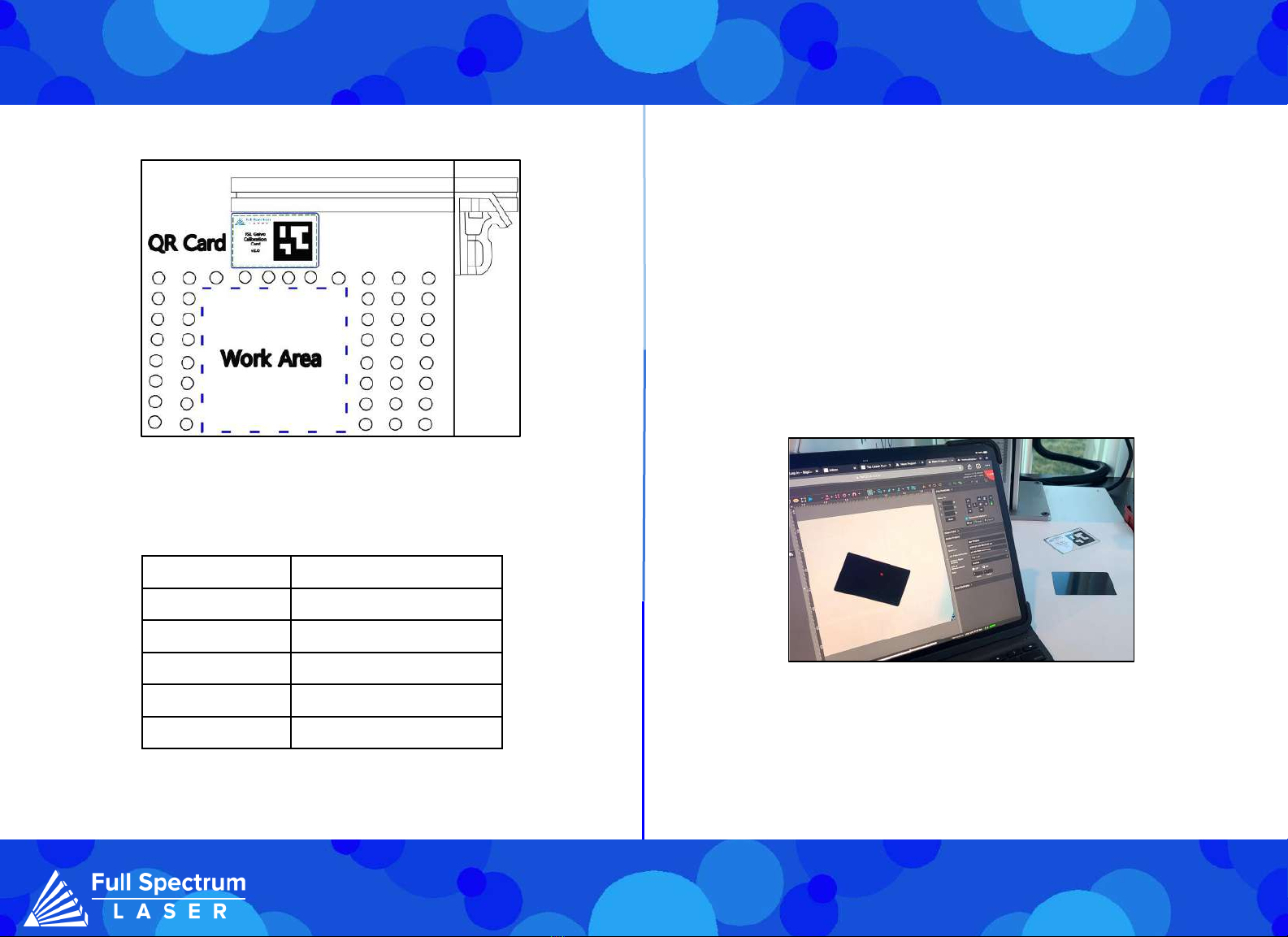
Lens Calibration:
Lens Size(mm) Working Area Approx. (mm)
163 110X110
210 140X140
254 175X175
330 220X220
420 300X300
Access the "Laser Tools" page by navigating to the Machine name, locate
Diagnostics, and then select Galvo Calibration. Alternatively, you can type the
following into your web browser: IP Address/setup.
Preparation:
Locate the QR card, have the side with the Calibration April Tag facing upwards.The
card should be placed outside the work area and within the camera’s view. It must be
placed parallel for accurate calibration. The size of the work area is determined by the
lens in use (refer to the chart below).
1. In the Laser Tools page, locate the Laser Focus and Lens Calibration section.
Ensure that the correct lens size is saved in the lens section.
2. Select Run Lens Calibration.
The laser diode will disappear, and the camera will slowly turn off. The diode will start
scanning the work area. After the calibration is finished, you will be given a pass or fail result.
If your test fails, adjust the lighting in your work area. If the lightning is too bright or too dark,
the camera will not be able to scan the workplace properly.
3. Once the test is passed, we recommend performing a camera capture to ensure the QR
card was positioned correctly. If the QR card was not placed parallel to the work area, the
camera may be calibrated improperly (as seen below).
In this image the QR card was placed in an angle, therefore the calibrated camera was
shifted by that angle. If this happens, you should re-run the calibration.
Once the machine is successfully calibrated, perform a mark and preview adjustment to
ensure the laser properly engraves in its new work area.
8

Mark Adjustment: Preview Adjustment:
Parameter Test:
Mark Adjustment is used to ensure your lens is calibrated properly. Keep the speed and power
settings unchanged.
1. Adjust the size parameters to the dimensions of the square that corresponds to the lens used.
2. Place a flat piece of test material under the laser for marking. Preview the square before
proceeding to ensure that only the test material will be marked.
3. Select "Mark Square".
Measure the marked square. It should match the size chosen earlier. If the lens calibration was not
done correctly, the marked square may be off by approximately 2mm. Re-run the lens calibration
and redo mark adjustment.
Please note that the top left corner of the square was intentionally cut..
4. Select "Save Mark Adjustment".
Without moving the previously engraved material, perform a preview adjustment.
1.Go to the Preview Adjustment window and select the "Preview Square" button.
2. Make use of the adjustment buttons to align the tracing made by the red dot precisely with
the marked square.
3. Finally, select "Save Preview Adjustment" to save the adjustments made.
Unsure of what settings you want to use for your materials, then try using the Laser Parameter
Test. Found directly under the Laser Tools tab on the Setup page. The Parameters Test will
generate a graph to test two chosen parameters using the set minimum and maximum values. The
size of the grid is determined by the intervals set, makes it easier to narrow down your selection.
The parameters you can test are: Power, Speed, Frequency, DPI, and Pulse Width. Pulse Width is
a parameter only used in MOPA machines. To access the Setup page, go to the Machine name,
then go to Diagnostics and select Galvo Calibration. Next, select the Parameters tab.
9
Andere Handbücher für MUSE FIBER GALVO 2
1
Dieses Handbuch passt für folgende Modelle
1
Inhaltsverzeichnis
Andere Full Spectrum Laser Drucker Handbücher


