
FuseBox AFDD060630B Gebrauchsanweisung
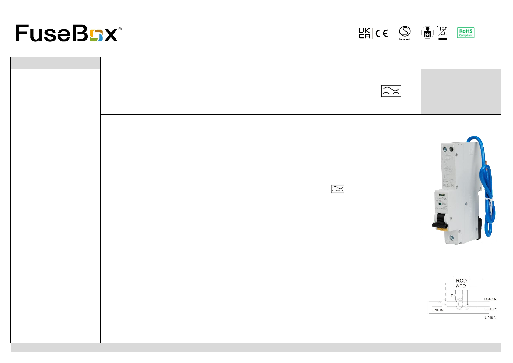
FUSEBOX 2021 AFDD 6KA 1P+N B CURVE 6_40A TECHNICAL DATA
RATING (A)
610 16 20 25 32 40
RATED RESIDUAL OPERATING CURRENT (IΔn) 30mA 30mA 30mA 30mA 30mA 30mA 30mA
PART NUMBER AFDD060630B AFDD061030B AFDD061630B AFDD062030B AFDD062530B AFDD063230B AFDD064030B
GTIN-13 5060523524457 5060523524464 5060523524471 5060523524488 5060523524495 5060523524501 5060523524518
STANDARD
NUMBER OF POLES
RATED VOLTAGE (Un/AC)
FREQUENCY (Hz)
RATED BREAKING CAPACITY (Icn)
RATED CURRENT (In)
TRIPPING CHARACTERISTICS
RESIDUAL CURRENT CHARACTERISTICS
RATED RESIDUAL OPERATING CURRENT (IΔn)
MECHANICAL ENDURANCE
PROTECTION DEGREE (IP)
MAXIMUM TERMINAL CAPACITY
RECOMMENDED TIGHTENING TORQUE (Nm)
FLYING NEUTRAL CABLE LENGTH (mm)
OVERVOLTAGE PROTECTION
MATERIAL
WEIGHT (1PC) Kg
INNER CARTON QUANTITY
OUTER CARTON QUANTITY
ENERGY LIMITING CLASS
MOUNTING
ORIGIN OF MANUFACTURE
CHINA
AFDD_RCBO (ARC FAULT DETECTION DEVICE)
>285V
PA6 (Nylon 6)
0.185
1
60
3
6, 10, 16, 20, 25, 32, 40
B CURVE : 3-5In
10,000
20
1-16mm² IN L / 1-10mm² OUT N L
2.5Nm IN L / 1.2Nm OUT N L
IEC 61009-1, BS EN 62606
0.03
1P+N (Switched)
230V
50/60
6000A (6kA)
TYPE A (AC AND PULSATING DC UP TO 6mA)
450 (can be cut to suit)
35mm Din rail mounting

FUSEBOX 2021 AFDD 6KA 1P+N B CURVE 6_40A TECHNICAL DATA
DIMENSIONS TRIPPING CHARACTERISTICS
B curve 3-5In
Connections
NEUTRAL CABLE CSA
6A 2.5 mm²
10A 2.5 mm²
16A 2.5 mm²
20A 2.5 mm²
32A 4.0 mm²
40A 4.0 mm²
www.fusebox.co.uk
Combined AFDD/RCBO
Combined AFDD RCBO (1P+N) with switched LINE and NEUTRAL.
Used for the protection against ARC FAULTS (SERIES AND PARALLEL), overload, short circuit
and earth leakage.
Type A for AC and pulsating DC sensitivity.
Short circuit capacity of 6kA with a maximum rating of 40A.
Designed to fit all FuseBox consumer units.
TESTING: Line and Neutral conductors do not have to be disconnected for IR (insulation
resistance) if the lever is in the OFF position.

FUSEBOX 2021 AFDD 6KA 1P+N B CURVE 6_40A TECHNICAL DATA
INSTRUCTIONS What to do if a combined AFDD/RCBO trips
1
2
3
2 Installation 4
2a combined AFDD/RCBO range designed to fit FuseBox consumer units and modular enclosures. 5 Once faulty appliance has been identified DO NOT USE until it has been checked.
2b 35mm top hat din rail mounting. 6 Switch AFDD/RCBO to ON position.
7If fault does not clear phone a qualified electrician to check installation
2d Cut, dress and connect cables as shown in the wiring diagram.
Lin (Line) terminal connect to the bus bar.
Neutral flying lead to the neutral terminal bar (can be cut to size to suit).
Green LED on Device operable
Red flash x1
Serial or parallel arc
detected
Yellow flash x2 Overvoltage >285V
3 Connections
Yellow flash x3
Residual current
detected
3a Before powering up the circuit check all connections are TORQUED. Red LED on Self test failed
NO LED
No supply voltage
4 Testing
Operation of the TEST button on combined AFDD/RCBO
Environment
WASTE ELECTRICAL PRODUCTS SHOULD NOT BE DISPOSED OF IN HOUSEHOLD WASTE.
RCBO TEST CONTACT YOUR RETAILER OR LOCAL AUTHORITY FOR RECYCLING INFORMATION
0.5IΔn RCBO will not trip
1Δn RCBO must trip within 300ms
5IΔn RCBO must trip within 40ms
Switch AFDD/RCBO to ON position and connect 1 appliance at a time to see which one trips the device.
LED Indication (table)
Connections
1a AFDD/RCBO must be installed by a qualified electrician in accordance with the current
IET Wiring Regulations BS 7671.
●●○●●○●●○●●○●●○
●
●○●○●○●○●○
●●●○●●●○●●●○●●●○●●●○
When newly fitted systems do not trip on the TEST button or using the MFT the problem is
normally caused by an earth to neutral fault on the circuit (PME supply).
Installers can easily check the AFDD/RCBO by removing the LOAD connections on the device
and applying power. If the TEST button works the fault is in the circuit.
Combined AFDD/RCBO ARE MANUFACTURED IN ACCORDANCE WITH IEC 61009-1 AND
MUST BE TESTED TO THIS SPECIFICATION USING A CALIBRATED TEST METER.
●
4a CONNECTIONS TO THE AFDD/RCBO DO NOT REQUIRE TO BE DISCONNECTED IF THE
LEVER IS IN THE “OFF” POSITION FOR IR TEST.
4b On completion of the installation, it must be tested in accordance with the latest edition
of the IET Wiring Regulations for Electrical Installations (BS 7671).
Reset tripped AFDD/RCBO to ON position
Note LED indication - see table below
Loose connections cause fires!!!!
1b Total load must not exceed the rating of the AFDD/RCBO or any additional limitation.
2c Clip securely on to the din rail making sure the din rail clip at the bottom is pushed in,
locking the AFDD/RCBO onto the din rail, ensure lever is in the OFF position.
Connect the load to the L OUT and N OUT terminals at the top of the AFDD/RCBO and the
Load earth to the terminal bar.
If AFDD/RCBO trips again then disconnect all appliances connected to this circuit.
Dieses Handbuch passt für folgende Modelle
6


