
Galactic GFZ18H-S1 Technisches Handbuch
Thank you very much for purchasing this Air Conditioner. Please
read this carefully before installing
and using this appliance and keep this manual for future reference.
use and installation instructions
GFZ18H-S1 / GCZ18H-S1
GFZ24H-S1 / GCZ24H-S1
GFZ36H-S1 / GCZ36H-S1
GFZ48H-S1 / GCZ48H-S1
GFZ60H-S1 / GCZ60H-S1
Welcome to use our product!
Thanks for trusting us.
Please read this manual carefully before installation!
Keep it properly for future use after installation!
Features of
The indoor unit’s
can be installed inside the ceiling conveniently.
Flexible Installation Options
According to the actual installation space,
the indoor unit
High Efficiency and Environment Friendly
New Refrigerant-R410A
R410A can protect the environment and do
not harm to the ozone layer.
24-hour Timer ON and OFF
This Timer can be set to automatically turn
the unit on or off within a 24-hour period.
Ceiling&Floor Air Conditioner
thickness is only 230mm,
can be installed in the ceiling
or on the floor. One unit, two installation
method.
Save Installation Space Mute Operation
The excellent fan design enable the airflow
to be quiet and smooth with minimum noise.
Various Refrigerant Pipe Connect Methods
The refrigerant pipe can be connected from 3
different directions(rear, right or top) .
More methods, more conveniently.
Self Recovery of Power Break
When the power supply is recovered after
break, all preset are still effective and the air-
conditioner can run according to the original
setting.
Fault Self-diagnose Function
When there is something wrong with the air-
conditioner, the micro computer could
diagnose the faults, which can be read from
the display and is convenient for maintenance.

Contents
--------------------------------------------------------------------------------2
-------------------------------------------------------------------3
Operation Manual
----------------------------------------------------------------------------------
-----------------------------------------------------------------------------------
Diagram of Refrigerant Cycle & Wiring
1.Refrigerant Flow Diagram ----------------------------------------------------------------7
2.Electrical Wiring Diagram ----------------------------------------------------------------7
Alert Symbols--------------------------------------------------------------------------------------1
Caution Statements
Composition of the Air-Conditioner
Special Remarks 5
Trouble shooting 5
Installation and Maintenance
------------------------------------------------------- -------- --------
---------------------------------- ---- ----------- -
--------------------------------------- --------- -------
- ---- -- --------------------------------------------------- -------
---- ---------------------------------------------------- -- ------
------------------------------------------------------------------ ---
------ ------------------------------------------ -----------------
--- ------------------------------------ ------------------
--------------------------------------------------- ---------------------- 15
----------------------------- ------------------- ---------------------
---------------------------------- ---------------------
.1 Installation Sites ---------------------------------------------- --------------------
.2 Installation of the Outdoor Unit ----------------------------- --------------------------
------------------------------------------------------ ----- ----------------- 18
9.1 Flaring with Tube Expander -------------------------------------------- --------------------- 18
9.2 Connecting Tubing Between Indoor and Outdoor Units ------------------------------------ ------- 18
9.3 Heat Insulation of the Refrigerant Tube --------------------------------------------------- ------ 18
9.4 Taping the Tubes ------- ------------------------------------------------------------- ------- 18
9.5 Finishing the Installation ------ ------------------------------------------------------- -------- 18
10 --------------------------------------------------------------------- --- 18
10.1 Air Purging with a Vacuum Pump ------------------------------------------------------ --- 18
10.2 Leak Test --------------- ------------------------------------------------------------ ------ 19
10.3 Tidy Up the Tubing ------- ----------------------------------------------------------- -------- 19
10.4 Test Run --------------- ------------------------------------------------------------- ------ 19
10.5 Common-------------------------------------------------------------------------------- - 20
1. Safety Notice 8
2. The Tools and Instruments for Installation 9
3. The Installation of the Indoor Unit 9
3.1 Before Installation 9
3.2 Installation Location 11
3.3 Installation 11
4. Refrigerant Pipe 14
4.1 The Pipe Material 14
4.2 The Connection of the Pipe 14
5. Drain Piping
6. Electrical wiring 16
7. Attaching the Air Return Grille 16
. The Installation of the Outdoor Unit 17
. Refrigerant Tubing
. Air Purging and Test Run
--------- -
--------- -
--------- -
- --- --- -
------ - -
------------------------------------------------------------------------------
--------
------ --
----- --- -
--------
- --------
--------------------------------------------------------------------
--------
--------
-------
- --------- -
---------
-------
-------
--- -----
--- -----
--------
------ ------
--- -----
--- ----
--- -----
----------
--------------
---------
------------
--------------
------------
--------------
--------------
-------------
------------
--------------
-------------
-----------
-----------
-------------
------------
--
---
--
--
---
---
--
---
---
---
---
--
8
8 17
17 8
9
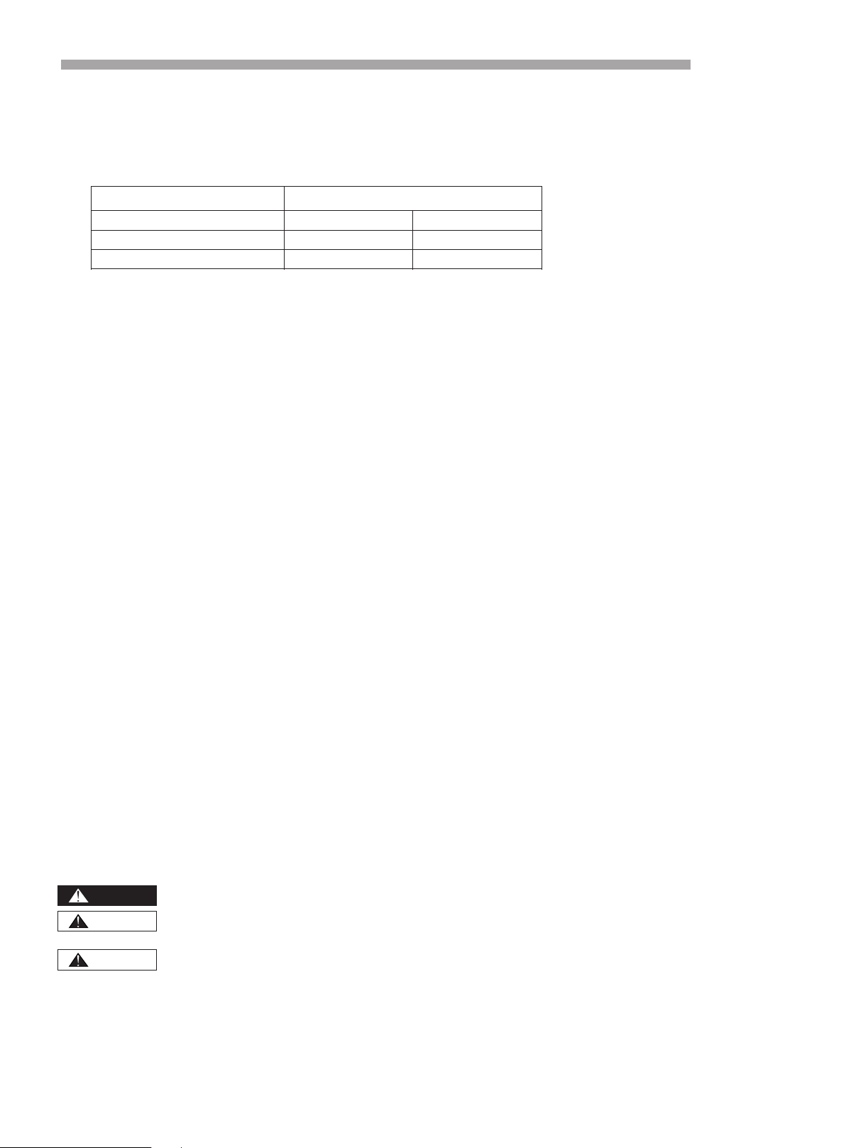
: The symbol refers to a hazard which can result in severe personal injury or death.
: The symbol refers to a hazard or an unsafe practice which may result in severe personal
injury or death.
: The symbol refers to a hazard or an unsafe practice which may result in personal injury,
product or property damage.
It refers to the remarks and instruction to the operation, maintenance, and service.
DANGER
WARNING
CAUTION
NOTE
Alert Symbols:
1
Contents
● This heat pump air conditioner has been designed for the following temperatures.
Operate the heat pump air-conditioner within this range.
Outdoor Working Temperature(℃)
Maximum
Minimum
Cooling Operation
48
-15
Heating Operation 24 -15
Storage condition: Temperature -25~60℃
Humidity 30%~80%
We recommend that this air-conditioner be installed properly by qualified installation technicians in
accordance with the installation instructions provided with the unit.
Before installation, check if the voltage of the power supply in your home or office is the same as the voltage
shown on the nameplate.
You must not carry on any transformation to this product, otherwise, it may possibly
cause such consequences as the water leakage, the breakdown, the short-circuit, an
electric shock, fire, etc.
The work such as tube line welding, etc. should be carried out far away from the
flammable explosive material vessels, including the air-conditioner refrigerant, to
guarantee the security of the site.
To protect the air-conditioner from heavy corrosion, avoid installing the outdoor unit
where salty seawater can splash directly onto it or in sulphurous air near a spa. Do
not install the air-conditioner where excessively high heat-generating objects are
placed.
Never use gasoline or other inflammable gas near the air-conditioner, which is very
dangerous.
If the supply cord is damaged, it must be replaced by the factory or its service
department in case of danger.
The place where this product is installed must have the reliable electrical earth facility
and the equipment. Please do not connect the grounding of this product to various kinds
of air-feeding tube lines, the drain lines, the lightning protection facility as well as other
tube lines to avoid receiving an electric shock and damages caused by other factors.
Wiring must be done by a qualified electrician. All the wiring must comply with the local
electrical codes.
Consider the capacity of the electric current of your electrical kilowatt-hour meter wires
and socket before installation.
The power wire where this product is installed is supposed to have the independent
leakage protective device and the electric current over-load protection device which are
provided for this product.
The appliance is not to be used by persons (including children) with reduced physical,
sensory or mental capabilities, or lack of experience and knowledge, unless they have
been given supervision or instruction. Children should be supervised not to play with
the appliance.
Means for disconnection, which can provide full disconnection in all poles, must be
incorporated in the fixed wiring in accordance with the wiring rules.
Do not turn the air-conditioner on and off from the power main switch. Use the
ON/OFF operation button.
Do not stick anything into the air inlet and air outlet of both the indoor and
outdoor units. This is dangerous because the fan is rotating at a high speed.
Do not cool or heat the room too much if babies or invalids are present.
Caution Statements
2
DANGER
WARNING
Read this manual carefully before using this air-conditioner. If you still have any
difficulties or problems, consult your dealer for help.
The air-conditioner is designed to provide you with comfortable room conditions. Use
this unit only for its intended purpose as described in this instruction manual.
WARNING
CAUTION
ON/OFF
MODE FAN
SWING
SWING
SLEEP SUPER
SMART IFEEL DIMMER
TIMER ON TIMER OFF CLOCK
ON
OFF
ON
OFF
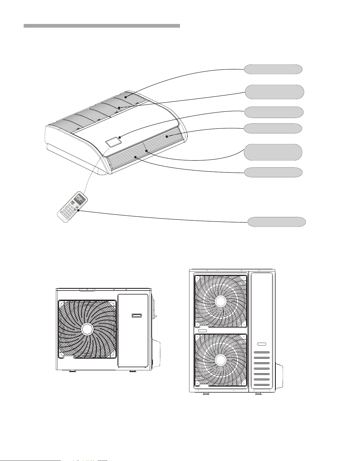
Air Outlet
Air Intake
Vertical Louver
Horizontal Louver
Wireless Remote Controller
Filter
Display Panel
(Inside of Air Intake)
(Inside of Horizontal Louver)
3
Composition of the Air-conditioner
Indoor Unit
Outdoor Unit
48K,60K
18K,24K,36K
Notes:
Figures in the manual are only simple representation of the appliance, its may not comply with the appearance
of the air conditioner you purchased.
Vertical adjustment louver swing automatically function is only available for some models.
4
Composition of the Air-conditioner
The figures in this manual are based on the external view of a standard model.
Consequently, the shape may differ from that of the air conditioner you have selected.
* It can be set or canceled by professional after-sale stuff.
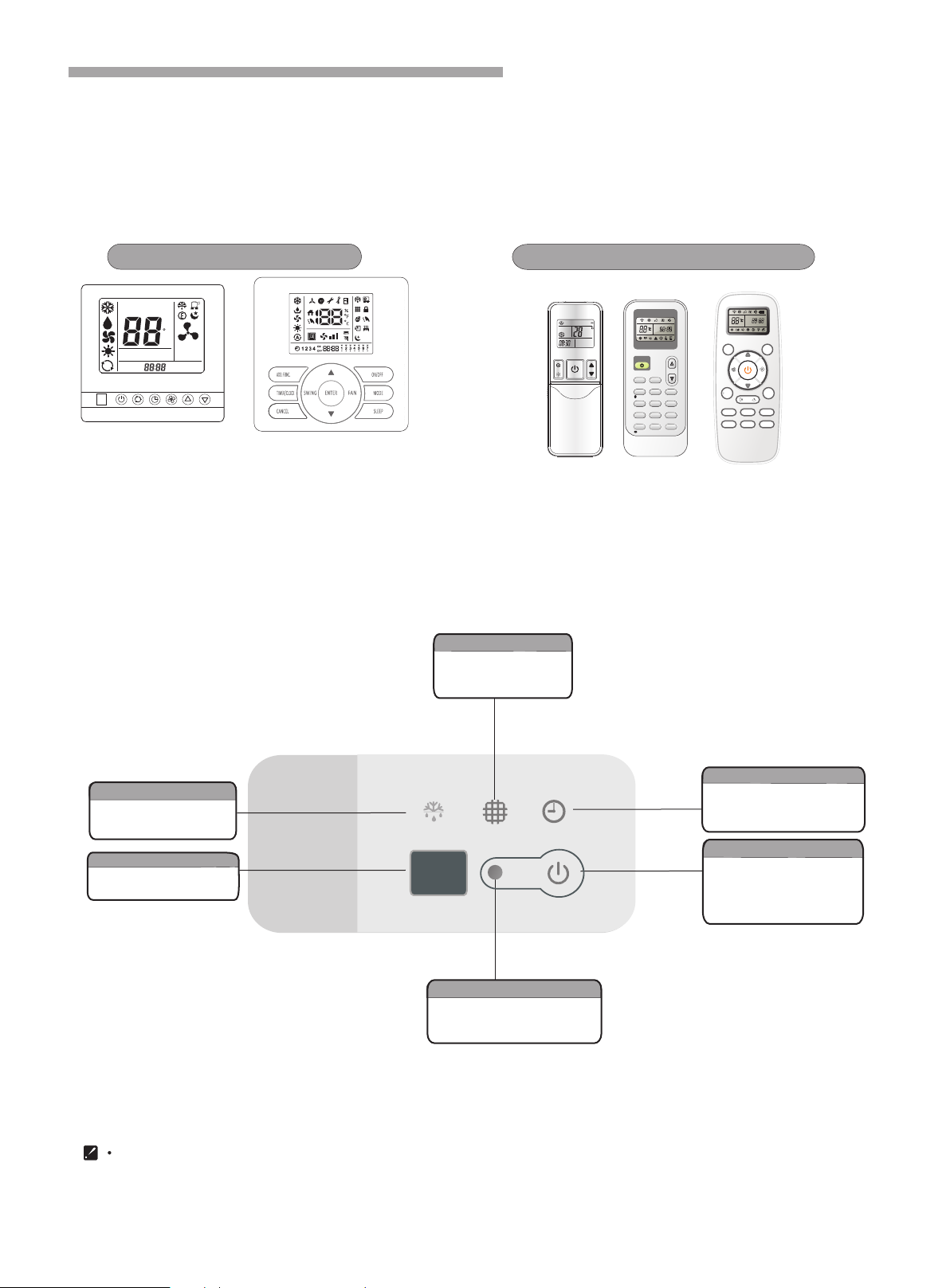
Display Panel
It lights on when timer is in
use.It lights off when timer
finishes.
It lights on when the filter
should be cleaned.
The filter clean is reset if press
the switch.
Press it the appliance will be stopped
when the unit is runing;
Press it for 5s,the appliance will be
forced cooling when the unit is OFF.
It lights on during the defrost.
It lights off when defrost
finishes.
Receives signal from the
remote controller.
Timer indicator ( )Green
Filter clean* ( )Yellow
Emergency switch
Defrost indicator ( )Green
Signal receiving section
It lights on during operation.
It lights off all when setting
SLEEP mode.
Run indicator ( )Red
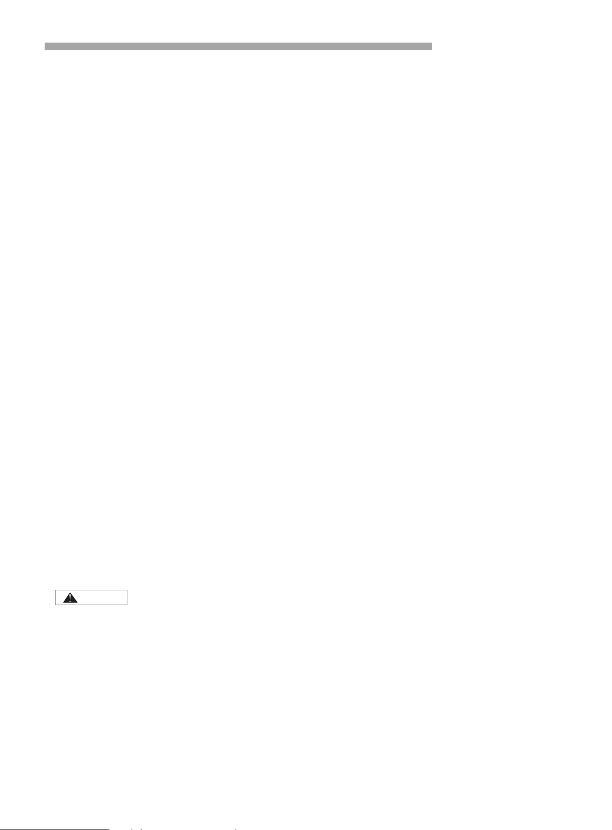
Wire remote controller Wireless remote controller
You can control the air-conditioner with the wire remote controller or wireless remote controller.
It is used for controlling power ON/OFF,setting the running mode, temperature,fan speed and other functions.
There are different types of remote controllers can be selected.
Operate instruction will be further specified in remote controller's manual separately.
Please read it carefully before using this appliance and keep it for future reference.
SET TEMP
ROOM
TEMP
C
AUTO
NO
.
TIMER ON
TIMER OFF
SET TIMER
A
Remote controller(optional)
ON/ OFF
MODE FA N
SLEE P SUP ER
SMART I FEE L DIM MER
TIME R ON TIM ER OFF CLOC K
ON
OFF
ON
OFF
SWIN G
SWIN G
ON
OFF
MODE
SMART
QUIE T DIM MER
ECON OMY
FEEL
SUPE R
FAN SPE ED
CLOC K
TIME R ON
TIME R OFF
SLEE P
TEMP.
TEMP.
确定
Operation Manual
Special remarks
·Cooling operation
The fan of the indoor unit will never stop running. It remains running even if the compressor stops working.
·Heating operation
Since the air conditioner carries out the heating operation by drawing on the heat of the outside air (through
heating pump), the heating capacity may decrease if the temperature outside the room is too low. If the
heating effect is not so satisfying, use some other heating device together.
·Anti-freezing function during cooling
When the temperature of the air from the indoor outlet is too low, the unit will run for some time under the
fan mode, to avoid frost or ice forming in the indoor heat exchanger.
·Cold air prevention
In several minutes after the heating mode is started, the fan of the indoor unit will not run until the heat
exchanger of the indoor unit reaches a high enough temperature. That is because cold air prevention system
is operating.
·Defrosting
When the outdoor temperature is too low, frost or ice may form in the outdoor heat exchanger, reducing
heating performance. When this happens, a defrosting system of the air conditioner will operate. At the same
time the fan in the indoor unit stops(or runs at a very low speed in some cases), a few minutes later, the
defrosting is over, and the heating operation restarts.
·Blow out the survival heating air
When stop the air conditioner in normal operation, the fan motor would run in low speed for a while to blown
out the survival heating air.
·Self Recovery of Power Break
When the power supply is recovered after break, all preset are still effective and the air-conditioner can run
according to the original setting.
Troubleshooting
When overflow of drain water from the indoor unit occurs, stop the operation and contact your contractor.
When you smell or see white smoke coming from the unit, turn OFF the main power supply and contact
your contractor.
1. If Trouble Still Remains ...
If the trouble still remains even after checking the following, contact your contractor and inform them of the
following items.
(1)Unit Model Name
(2)Content of Trouble
2. No Operation
Check whether the SET TEMP is set at the correct temperature.
CAUTION
3 minutes protect after compressor stop
For protect compressor, there are at lest 3 minutes stopping after compressor stop.
minutes protect
Compressor must run 5 minutes at least once running. In the 5 minutes, compressor will not stop
even the room temperature reach the setting point unless you use remoter to turn off the unit.
·
· 5
5
6
Operation manual
3. Not Cooling or Heating Well
Check for obstruction of air flow of outside or inside units.
Check if too much heat source exists in the room.
Check if the air filter is clogged with dust.
Check to see if the doors or windows are opened or not.
Check if the temperature condition is not within the operation range.
4. This is Not Abnormal
Smells from indoor unit
Smell adheres on indoor unit after a long period of time. Clean the air filter and panels or allow a good
ventilation.
Sound from Deforming Parts
During system starting or stopping, an abrading sound might be heard. However, this is due to thermal
deformation of plastic parts. It is not abnormal.
Steam from Outdoor Heat Exchanger
During defrosting operation, ice on the outdoor heat exchanger is melted, resulting in making steam.
Dew on Air Panel
When the cooling operation continues for a long period of time under high humidity conditions(higher than
27℃/80%R.H.), dew can form on the air panel,
Refrigerant Flow Sound
While the system is being started or stopped, sound from the refrigerant flow may be heard.
please set the appliance at high fan speed and adjust louvers
to the max. angle.
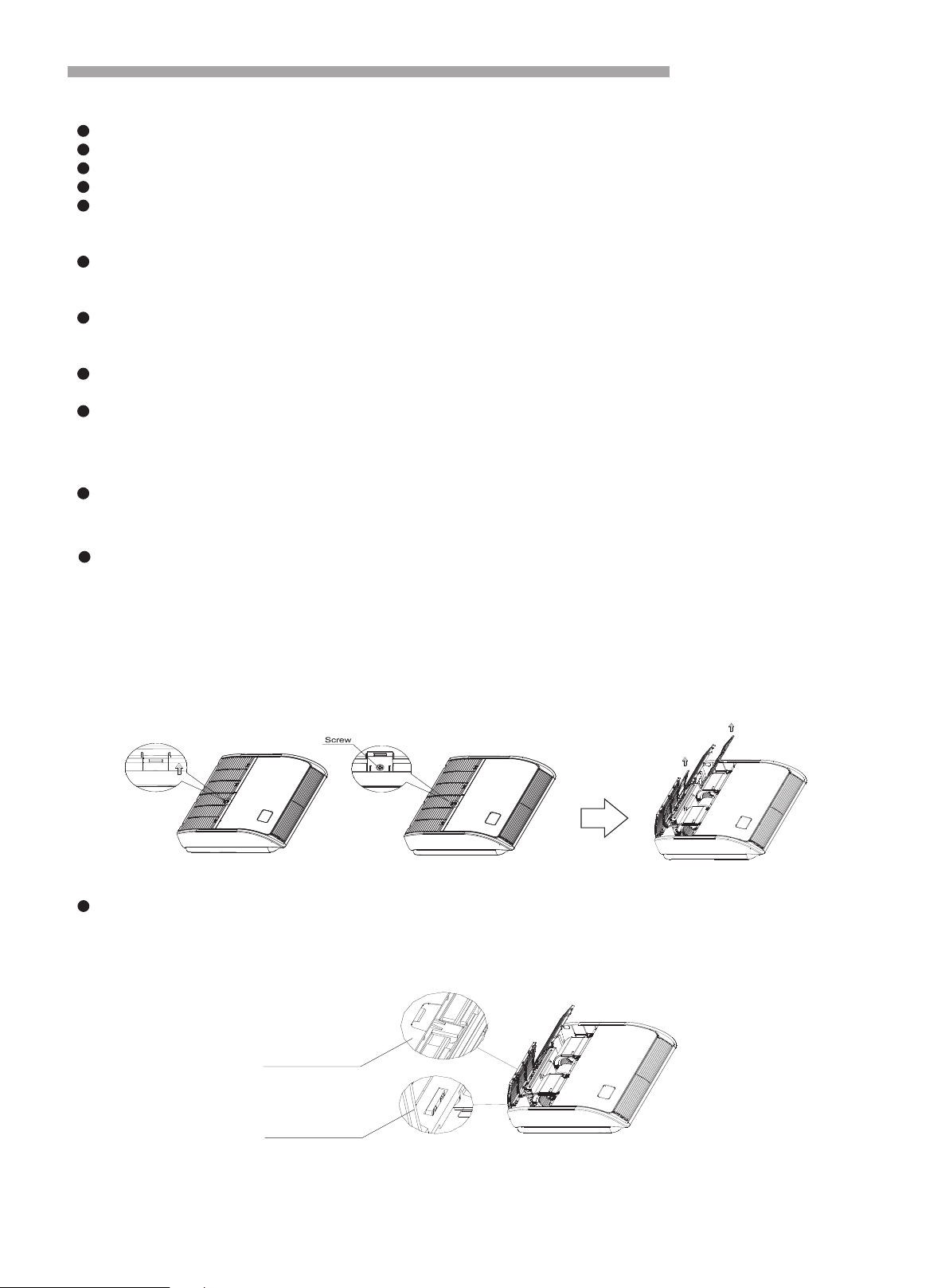
5.Filter removing and installing
Removing filter from air return grille
Reset the filter
nsert the filer to the grille and aim the bottom hooks. Pay attention to grille top hooks is locked .
Fix four screws .
Take out the air filter according the following steps.
Step1
Slide the air return grille holding knobs(4 places) , then remove the holding screws(4 or 6 places) as shown
by the arrow mark.
Step2
Open the air return grille to an angle of more than 45°and take out the air filter from the air inlet grille by
supporting the air grille and lifting the air filter after detaching the filter from the hinges.
Step1:I
Step2:
Step3:The intake grille is attached.
step 1
bottom hook
top hook
step 2
6
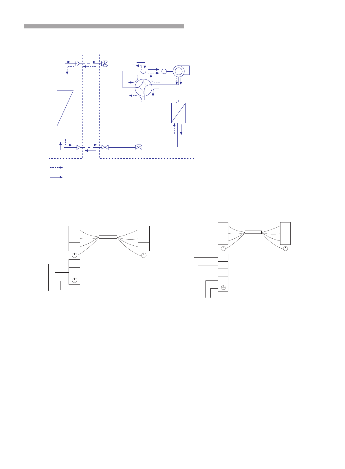
Diagram of refrigerant cycle & Wiring
1.REFRIGERANT FLOW DIAGRAM
2.ELECTRICAL WIRING DIAGRAM
7
Gas piping
Wide service valve
Compressor
Accumulator
4-way valve
Heat exchanger
Liquid piping
Heating cycle
Cooling cycle
INDOOR UNIT OUTDOOR UNIT
Heat exchanger
EEV
Service valve
Outdoor unit Indoor unit
Terminal Terminal
SI
L
N
SI
L
N
Power connecting cord
N
L
Power supply
Power supply
Outdoor unit Indoor unit
Terminal Terminal
SI
L
N
SI
L
N
Power connecting cord
N
W
V
U
48K/60K
18K/24K/36K
Dieses Handbuch passt für folgende Modelle
9
Inhaltsverzeichnis
Andere Galactic Klimaanlage Handbücher


