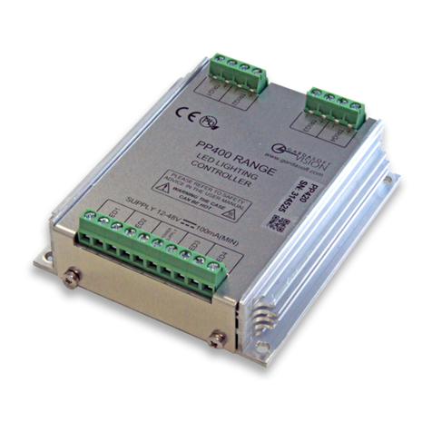
GARDASOFT CC320 Bedienungsanleitung

CC320
Trigger Timing Controller
USER MANUAL
Revision 08
Gardasoft Vision Ltd
Trinity Court, Swavesey
Cambridge, CB24 4UQ, UK
Pyramid Imaging
Pyramid Imaging
945 East 11th Ave
Tampa, FL 33605
https://pyramidimaging.com


1DISCLAIMER .................................................................................................................... 4
2SAFETY .............................................................................................................................. 4
3GETTING STARTED ........................................................................................................ 5
4MECHANICAL FIXING ................................................................................................... 6
5CONNECTIONS................................................................................................................. 7
5.1 GENERAL....................................................................................................................... 7
5.2 POWER SUPPLY ............................................................................................................. 7
5.3 DIGITAL INPUTS ............................................................................................................ 7
5.4 DIGITAL OUTPUTS ......................................................................................................... 8
6OPERATION ...................................................................................................................... 9
6.1 INPUT MODES................................................................................................................ 9
6.2 OUTPUT MODES .......................................................................................................... 10
6.3 EXAMPLES................................................................................................................... 13
6.4 COLD BOOT ................................................................................................................. 19
6.5 CONFIGURATION FORM ............................................................................................... 20
7KEYPAD CONFIGURATION ........................................................................................ 21
7.1 STARTUP ..................................................................................................................... 21
7.2 COLD START................................................................................................................ 21
7.3 CONFIGURATION ......................................................................................................... 21
8ETHERNET SETUP......................................................................................................... 26
8.1 CONNECTION ............................................................................................................... 26
8.2 IP ADDRESS................................................................................................................. 26
9WEBPAGE CONFIGURATION..................................................................................... 30
9.1 MAIN PAGE ................................................................................................................. 30
9.2 CHANNEL CONFIGURATION PAGES.............................................................................. 30
10 UDP AND TCP/IP CONFIGURATION ......................................................................... 31
10.1 COMMUNICATION .................................................................................................... 31
10.2 COMMAND STRUCTURE ........................................................................................... 31
10.3 COMMANDS ............................................................................................................. 32
10.4 COMMAND SUMMARY ............................................................................................. 36
A. TIMING............................................................................................................................. 37
B. ERROR CODES ............................................................................................................... 38

1Disclaimer
Except as prohibited by law:
All hardware, software and documentation is provided on an “as is” basis.
It is essential that the user ensures that the operation of the product is suitable for their
application.
The user must ensure that incorrect functioning of this equipment cannot cause any
dangerous situation or significant financial loss to occur.
Gardasoft Vision Ltd and Gardasoft Products Ltd do not accept any liability for
consequential loss of any kind.
All trademarks acknowledged.
Hardware, software and documentation are Copyright 2007-2011 Gardasoft Products Ltd.
Hardware manufactured by Gardasoft Vision Ltd under license.
2Safety
2.1.1 General
Please read this before using the CC320 family of products. If in doubt, contact your distributor
or Gardasoft Vision.
The CC320 must not be used in an application where its failure could cause a danger to personal
health or damage to other equipment.
If the equipment is used in a manner not specified by the manufacturer, the protection provided
by the equipment may be impaired.
2.1.2 Electrical
The user must ensure that the potential difference between any combination of applied signals
does not exceed the supply voltage. WARNING: Higher voltages may cause a danger to personal
health.
The CC320 does not have complete tracking isolation of inputs and outputs.
Transients caused by inductive loads must be suppressed external to the CC320.

3Getting Started
Read the sections on Safety and Operation and check the CC320 fulfils your requirements.
Mount the CC320 as described in “Mechanical Fixing” using a DIN rail or the mounting holes.
Connect the CC320 as in the section on Connections. When the CC320 powers up it should show
two alternating lines on the display to indicate that it is operating properly. Three indicator LEDs
on the outputs should be pulsing in sequence every second.
Check that inputs and outputs are working correctly as described in Troubleshooting.
If required, connect Ethernet to the CC320 and set it up according to the Ethernet section.
Read the section on “Operation.” Use the keypad, a web browser or the CC320 demo program
(available from www.gardasoft.com) to configure the unit.
Visit www.gardasoft.com for Application Notes giving additional information on the use of the
CC320.
Throughout this manual, references to the CC320 refer to all variants in the CC320 range unless
otherwise stated.
The symbol “s” is used to indicate seconds, “ms” for milliseconds and “us” for microseconds.
4Mechanical Fixing
The CC320 does not have an IP rating and should be mounted so that moisture and dirt cannot
enter the unit.
The operating temperature range is 5octo 60oc.
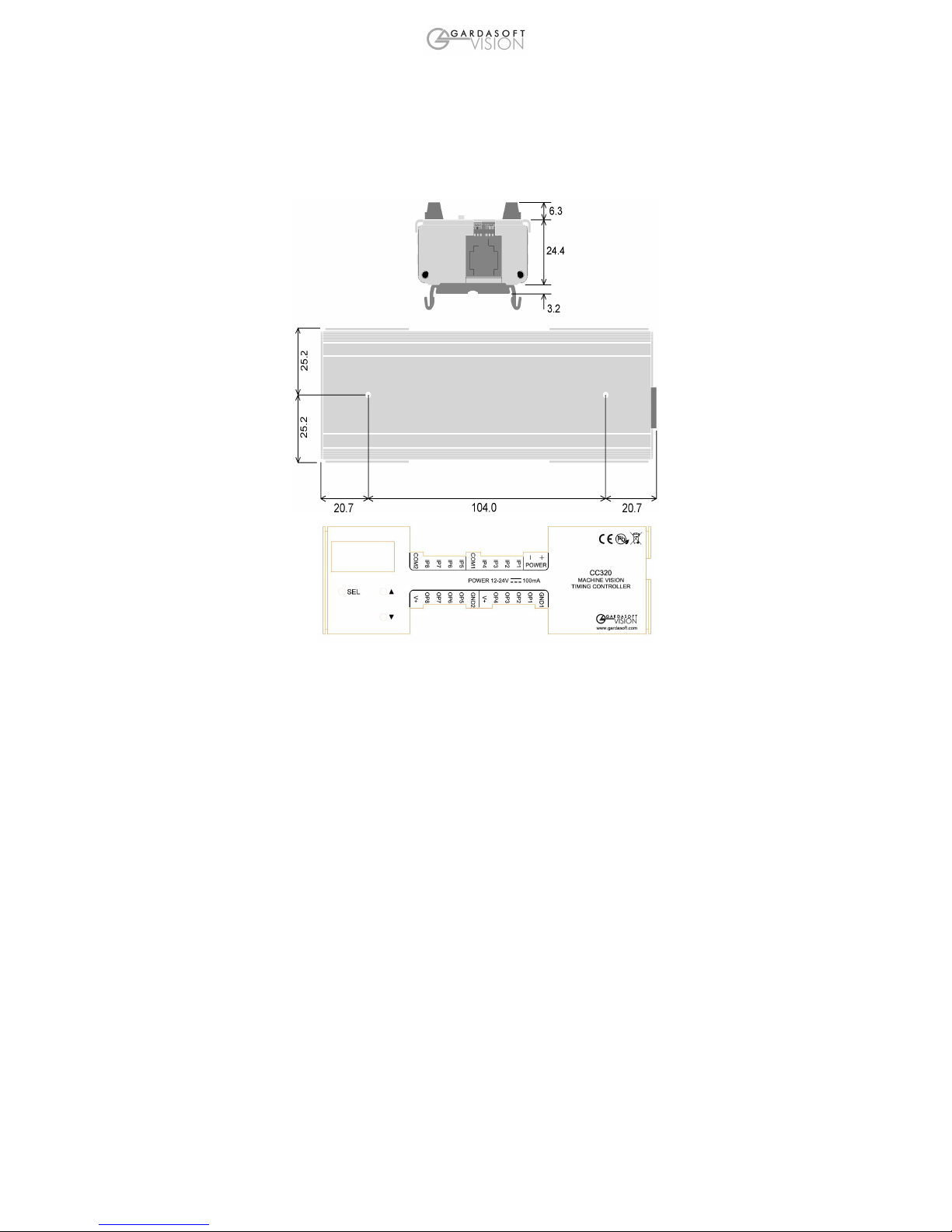
The CC320 can be mounted onto a panel using the threaded holes in the base, see diagram
below. The PP703 kit is available for mounting the CC320 on a DIN rail. The top drawing shows
the optional DIN rail fitted. Dimensions are in millimetres.
The CC320 enclosure is a fire enclosure as long as the following conditions are met:
•The Ethernet connector must not be facing downwards
•The mounting holes on the underside must be covered or have a screw fitted.

5Connections
5.1 General
All connections except Ethernet are available on screw terminals.
5.2 Power Supply
The power supply must be 12VDC to 24VDC regulated. The maximum current required is
100mA. The maximum heat dissipation is 2.4W.
5.3 Digital Inputs
The state of each input is shown on an LED next to the connector.
The inputs have a common negative connection, in two groups of four.
Connector Function
Opto-Coupled Input Details POWER
+
Power supply 12V to 24V
POWER - Power supply 0V
IP1 Input 1 positive
IP2 Input 2 positive
IP3 Input 3 positive
IP4 Input 4 positive
Operating Conditions COM1 Common negative for inputs 1, 2, 3, 4
5V ∗VIP ∗24V Logic 1 IP5 Input 5 positive
VIP ∗2V Logic 0 IP6 Input 6 positive
VF 1.5V typ IP7 Input 7 positive
IIN=1.8mA @ VIP=5V IP8 Input 8 positive
IIN=11.3mA @ VIP=24V COM1 Common negative for inputs 5, 6, 7, 8

5.4 Digital Outputs
The state of each output is shown by an LED indicator next to the connector.
The operational details are shown in the table below:
Connector Function
Open Drain Output Details
The voltage across the output must
not be greater than 24V and the
output can only sink up to 50mA.
If the output is shorted to a voltage
higher than 5V then the output may
be damaged.
Do not draw more than 50mA from
the +VE connections as this can
affect the internal operation of the
controller.
GND1 Common 0V for outputs 1, 2, 3, 4
OP1 Output 1 open drain
OP2 Output 2 open drain
OP3 Output 3 open drain
OP4 Output 4 open drain
+VE Low power regulated output. Maximum
source current 50mA.
GND2 Common 0V for outputs 5, 6, 7, 8
OP5 Output 5 open drain
OP6 Output 6 open drain
OP7 Output 7 open drain
OP8 Output 8 open drain
+VE Low power regulated output. Maximum
source current 50mA.
Note that the +ve signals are low power supply outputs. These are just to be used for low current
pull ups.
5.4.1 Ethernet Connector
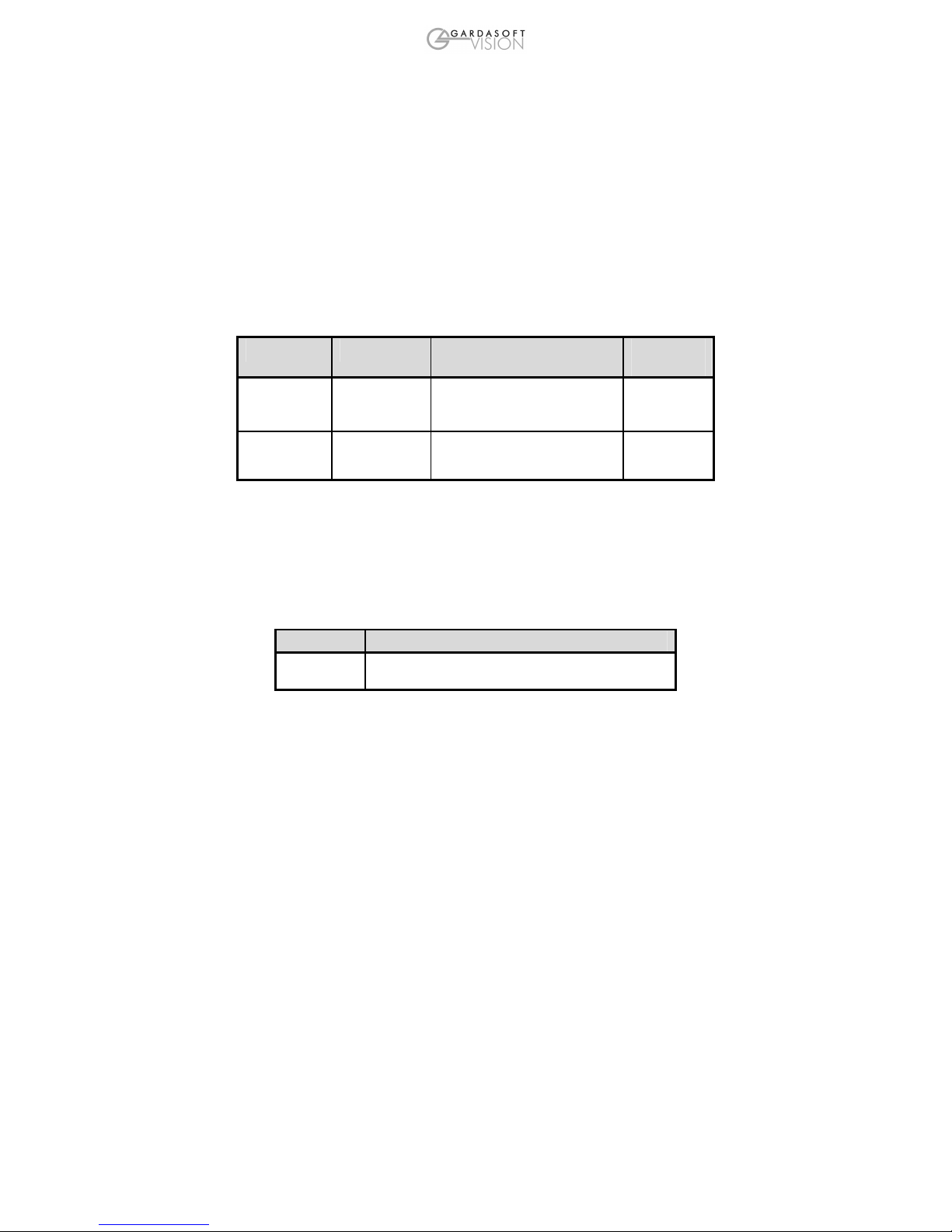
The RJ45 Ethernet connector requires a straight through cable to connect into a network switch,
hub or router. It runs at 10Mbits per second.
6Operation
The CC320 Trigger Timing Controller has eight digital inputs and eight digital outputs.
All outputs operate independently and are configured separately. Configuration is very flexible to
provide solutions for a wide variety of timing problems.
The configuration can be saved in non-volatile memory so that the CC320 resumes operation
after a power cycle.
The state of each input and output is shown on an LED next to the connector. Pulses are
stretched – a 10us pulse is shown as a 100ms pulse on the LED, so that it is visible to the user.
6.1 Input Modes
All inputs are general purpose trigger inputs except for IP1 and IP2, which can be used for an
encoder or as general inputs.
6.1.1 Encoder Operation
The CC320 supports two types of encoder.
Mode Connections Operation Max
frequency
EN 1 - one
wire encoder
IP1 is QEA Simple encoder provides position
information. All movement is
assumed to be forward.
700KHz
EN 2 – two
wire encoder
IP1 is QEA
IP2 is QEB
Quadrature encoder provides
position and direction information.
200KHz
For 2 wire encoders the CC320 correctly handles reversed movement. When the belt is in a
reversed position:
•the letter “b” is displayed on the front panel
•triggers for PEt and PEE modes (see below) are ignored
•output pulses in PtE, Pet and PEE modes are not duplicated
6.1.2 Free Running Trigger
An internal input (IP0) can be used as a periodic trigger.
The following parameter can be set.
Parameter Use
Period The period (inverse of the frequency) of the simulated
trigger. 0 disables the free running timer.
For example a period of 20ms could be set, which would result in a 50Hz trigger. This can be
used to trigger pulses on any of the outputs.

6.2 Output Modes
Each output operates independently. By combining which outputs are triggered by which inputs
and which mode each output is in, it is possible to configure complex sequences of operation.
Several outputs can be triggered by one input to give synchronous operation, or from separate
inputs to give asynchronous operation of different functions.
For each output, the following parameters can be set.
Parameter Use
Mode Specifies how the output operates.
Input Specifies which input is used for triggering. An output signal OP1 to
OP8 can also be used as a trigger. This parameter can be:
0 for the free running timer
1 to 8 for IP1 to IP8
9 to 16 for OP1 to OP8
Gate Input Specifies an input which enables/disables the output. This is also used to
specify the number of pulses in “burst” mode. This parameter can be:
0 for none
1 to 8 for IP1 to IP8
9 to 16 for OP1 to OP8
<number of pulses> for burst mode
Pulse Delay Specifies the delay from trigger to pulse output. This can either be a
time period or a number of encoder pulses, depending on the mode.
Pulse Width Specifies the width of the pulse output. This can either be a time period
or a number of encoder pulses, depending on the mode.
Retrigger time The retrigger time is the minimum time from when an output is
triggered to the next time. This can be used to debounce noisy inputs or
when a product sensor fires more than once for one product. The
retrigger time uses the same dimension (encoder pulses or time period)
as the Pulse Delay.
Flags Specifies other options.
When pulsing, the Pulse Delay and Pulse Width parameters can either be fixed times or can be a
number of encoder pulses.
The following operating modes are available for each output. The Mode Number is used for
Ethernet commands. The Mode Name is used when configuring using the keypad.
Andere Handbücher für CC320
1
Inhaltsverzeichnis
Andere GARDASOFT Controller Handbücher

GARDASOFT
GARDASOFT CL190 Bedienungsanleitung

GARDASOFT
GARDASOFT TR-RT Series Bedienungsanleitung

GARDASOFT
GARDASOFT RT 20 Series Bedienungsanleitung

GARDASOFT
GARDASOFT PP600 Bedienungsanleitung

GARDASOFT
GARDASOFT PP600F LED Bedienungsanleitung

GARDASOFT
GARDASOFT GigE Vision TR-RC Series Bedienungsanleitung

GARDASOFT
GARDASOFT OC-G-5646-2-ET Bedienungsanleitung

GARDASOFT
GARDASOFT TR-CL Series Bedienungsanleitung

GARDASOFT
GARDASOFT RT Series Bedienungsanleitung

GARDASOFT
GARDASOFT RC100 Bedienungsanleitung