GEA Bock HG12P/75-4 Bedienungsanleitung

D
GB
F
E
I
Ru
1
09652-06.2015-DGbFEIRu
engineering for a better world
GEA Bock Compressor HG12P
Assembly instructions
HG12P/75-4 HG12P/60-4 S HGX12P/75-4 HGX12P/60-4 S
HG12P/90-4 HG12P/75-4 S HGX12P/90-4 HGX12P/75-4 S
HG12P/110-4 HG12P/90-4 S HGX12P/110-4 HGX12P/90-4 S
HG12P/110-4 S HGX12P/110-4 S

2
D
GB
F
E
I
Ru
09652-06.2015-DGbFEIRu
1 Safety 4
1.1 Identicationofsafetyinstructions
1.2 Qualicationsrequiredofpersonnel
1.3 Generalsafetyinstructions
1.4 Intendeduse
2 Product description 6
2.1 Shortdescription
2.2 Nameplate
2.3 Typekey
About these instructions
Readtheseinstructionsbeforeassemblyandbeforeusingthecompressor.Thiswillavoidmisunder-
standings andpreventdamage.Improperassemblyanduseofthecompressorcanresultinserious
orfatalinjury.
Observethesafetyinstructionscontainedintheseinstructions.
Theseinstructionsmustbepassedontotheendcustomeralongwiththeunitinwhichthecompres-
sorisinstalled.
GEABockGmbH
72636Frickenhausen
GEABockGmbH
Benzstraße7
72636Frickenhausen
Germany
Telephone+49702294540
Fax +4970229454137
www.gea.com
Manufacturer
Contact
Contents Page

D
GB
F
E
I
Ru
3
09652-06.2015-DGbFEIRu
Contents Page
3 Areas of application 8
3.1 Refrigerants
3.2 Oilcharge
3.3 Limitsofapplication
4Compressor assembly 10
4.1 Storageandtransport
4.2 Settingup
4.3 Pipeconnections
4.4 Pipes
4.5 Layingsuctionandpressurelines
4.6 Operatingtheshut-offvalves
4.7 Operatingmodeofthelockableserviceconnections
5 Electrical connection 13
5.1 Informationforcontactorandmotorcontactorselection
5.2 Connectionofthedrivingmotor
5.3 Circuitdiagramfordirectstart230VΔ/400VY-->with MP10
5.4 ElectronictriggerunitMP10
5.5 ConnectionoftheelectronictriggerunitMP10
5.6 FunctionaltestoftheelectronictriggerunitMP10
5.7 Circuitdiagramfordirectstart230VΔ/400VY-->with INT69 G
5.8 ElectronictriggerunitINT69G
5.9 ConnectionoftheelectronictriggerunitINT69G
5.10 FunctionaltestoftheelectronictriggerunitINT69G
6 Commissioning 22
6.1 Preparationsforstart-up
6.2 Pressurestrengthtest
6.3 Leaktest
6.4 Evacuation
6.5 Refrigerantcharge
6.6 Start-up
6.7 Avoidingslugging
6.8 Connectionofoillevelregulator
7 Maintenance 24
7.1 Preparation
7.2 Worktobecarriedout
7.3 Sparepartsrecommendation
7.4 Accessories
7.5 Extractfromthelubricantstable
7.6 Decommissioning
8 Technical data 26
9 Dimensions and connections 27
10 Declaration of conformity and installation 28
11 Service 29

4
D
GB
F
E
I
Ru
09652-06.2015-DGbFEIRu
1|Safety
1.2 Qualicationsrequiredofpersonnel
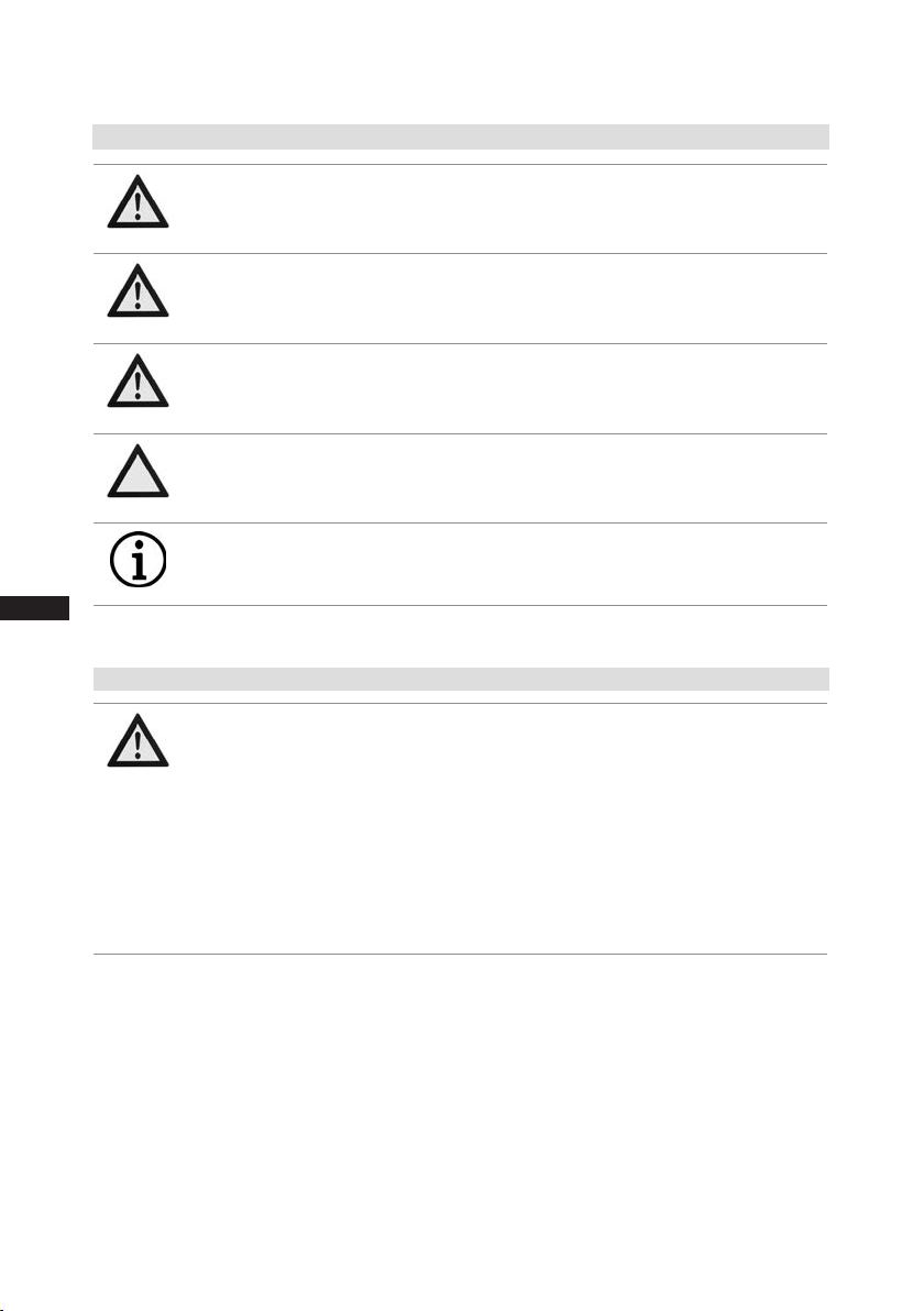
DANGER Indicates a dangerous situation which, if not avoided,
will cause immediate fatal or serious injury.
WARNING Indicates a dangerous situation which, if not avoided,
may cause fatal or serious injury.
CAUTION Indicates a dangerous situation which, if not avoided,
may cause fairly severe or minor injury.
ATTENTION Indicates a situation which, if not avoided,
may cause property damage.
INFO Important information or tips on simplifying work.
WARNING Inadequatelyqualied personnelposesthe riskof accidents,the
consequencebeingseriousorfatalinjury.Workoncompressors
isthereforereservedforpersonnelwhichisqualiedtoworkon
pressurized refrigerant systems:
•For example, a refrigeration technician, refrigeration mechatronic
engineer. As well as professions with comparable training, which
enables personnel to assemble, install, maintain and repair
refrigerationandair-conditioningsystems.Personnelmustbecapable
ofassessingtheworktobecarriedoutandrecognisinganypotential
dangers.
1.1 Identicationofsafetyinstructions:

D
GB
F
E
I
Ru
5
09652-06.2015-DGbFEIRu
1|Safety
1.4 Intended use
1.3 General safety instructions
WARNING Risk of accidents.
Refrigerating compressors are pressurised machines and as such
call for heightened caution and care in handling.
The maximum permissible overpressure must not be exceeded,
even for testing purposes.
Risk of burns!
- Depending on the operating conditions, surface temperatures of
over 60°C on the discharge side or below 0°C on the suction side
can be reached.
- Avoid contact with refrigerant necessarily.
Contact with refrigerant can cause severe burns and skin
damage.
WARNING The compressor may not be used in potentially explosive
environments!
These assembly instructions describe the standard version of the compressor named in the title
manufacturedbyGEA Bock.GEABockrefrigerating compressorsareintended for installationin a
machine(withintheEUaccordingtotheEU Directives 2006/42/EC MachineryDirective,97/23/EC
PressureEquipmentDirectiveand2006/95/EC–LowVoltageDirective).
Commissioningispermissibleonlyifthecompressorhasbeeninstalledinaccordancewiththeseas-
semblyinstructionsandtheentiresystemintowhichitisintegratedhasbeeninspectedandapproved
inaccordancewithlegalregulations.
Thecompressorsareintendedforuseinrefrigerationsystemsincompliancewiththelimitsof
application.
Onlytherefrigerantspeciedintheseinstructionsmaybeused.
Any other use of the compressor is prohibited!

6
D
GB
F
E
I
Ru
09652-06.2015-DGbFEIRu
2|Product description
• Semi-hermetictwo-cylinderreciprocatingcompressorwithoilpumplubrication.
• Suctiongascooleddrivemotor.
2.1 Short description
Fig.1
Fig.2
Oilsightglass
Valveplate
Cylindercover
Discharge
shut-offvalve
Oilpump
Terminalbox
Suction
shut-offvalve
Drivesection
Motorsection
DimensionandconnectionvaluescanbefoundinChapter9
Transporteyelet
Nameplate

D
GB
F
E
I
Ru
7
09652-06.2015-DGbFEIRu
2|Product description
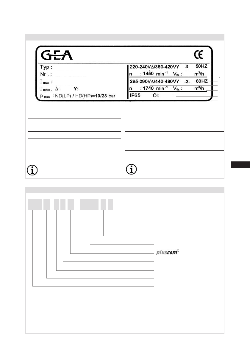
2.2 Name plate (example)
1 Typedesignation 6 Voltage,circuit,frequency
2 Machinenumber 7 Nominalrotationspeed
3 maximumoperatingcurrent 8 Displacement
4 Startingcurrent(rotorblocked) 9 Voltage,circuit,frequency
5 ND(LP):max.admissibleoperating 10 Nominalrotationspeed
pressure(g)Lowpressureside 11 Displacement
HD(HP):
max.admissibleoperating
12 Oiltypelledatthefactory
pressur
e(g)Highpressureside 13 Terminalboxprotectiontype
Observe the limits of application Electrical accessories can change
diagrams! the IP protection class!
50 Hz
}
60 Hz
}
/
HG 21 P 110- 4 SX
2.3 Type key (example)
¹) HG-HermeticGas-cooled(suctiongas-cooled)forthenormal-/airconditioningapplications
²) X
-Esteroilcharge(HFCrefrigerant,e.g.R134a,R404A/R507,R407C)
³) AdditionaldeclarationforPluscomcompressors
4) S - Morepowerfulmotor,e.g.forair-conditioningapplications
Motorvariant4)
Numberofpoles
Sweptvolume
³)
Numbersofcylinders
Size
Oilcharge²)
Series¹)
Typschild (Beispiel)
1
2
3
4
513
12
7
11
6
10
8
9
1 Typbezeichnung
2 Maschinennummer
3 maximaler Betriebsstrom
4 Anlaufstrom (Rotor blockiert)
5 ND (LP): max. zulässiger Stillstandsdruck
Saugseite
HD (HP): max. zulässiger Betriebsdruck
Hochdruckseite
Einsatzgrenzendiagramme beachten!
50 Hz
60 Hz
6 Spannung, Schaltung, Frequenz
7 Nenndrehzahl
8 Hubvolumen
9 Spannung, Schaltung, Frequenz
10 Nenndrehzahl
11 Hubvolumen
12 Werkseitig eingefüllte Ölsorte
13 Schutzart Klemmenkasten
10,6/6,1A
45A 26A
9,4
11,3
HGX12P/110-4S
AS35830A001
SE 55
AS35830A001
GEA Bock GmbH
72636 Frickenhausen, Germany
1
2
3
4
5
6
7
8
9
10
12
13
11
Fig.3

8
D
GB
F
E
I
Ru
09652-06.2015-DGbFEIRu
3|Areas of application
Thecompressorsarelledatthefactorywiththefollowingoiltype:
-forR134a,R404A/R507,R407C FUCHSRenisoTritonSE55
-forR22 FUCHSRenisoSP46
Compressorswithesteroilcharge(FUCHSRenisoTritonSE55)aremarkedwithanXinthetype
designation(e.g.HGX12P/110-4).
3.1 Refrigerants
• HFKW/HFC: R134a,R404A/R507,R407C
• (H)FCKW/(H)CFC: R22
3.2 Oil charge
3.3 Limits of application
INFO For refilling, we recommend the above oil types.
Alternatives: see lubricants table, Chapter 7.5
ATTENTION The oil level must be in the
visible part of the sight glass;
damage to the compressor is
possible if overfilled or under-
filled! Fig.4
max.
min.
0,5Ltr.
oillevel ~
~
ATTENTION Compressor operation is possible within the operating limits
shown in the diagrams. Please note the signicance of the
shaded areas. Thresholds should not be selected as design or
continuous operation points.
- Permissible ambient temperature (-20°C) - (+60°C).
- Max. permissible discharge end temperature 140°C.
-Max.permissibleswitchingfrequency8x/h.
- A minimum running time of 3 min. steady-state condition
(continuous operation) must be achieved.
For operation with supplementary cooling:
- Use only oils with high thermal stability.
- Avoid continuous operation near the threshold.
Foroperationwithfrequencyconverter:
- The maximum current and power consumption must not be
exceeded.Inthecaseofoperationabovethemainsfrequency,the
application limit can therefore be limited.
When operating in the vacuum range, there is a danger of air
entering on the suction side. This can cause chemical reactions,
a pressure rise in the condenser and an elevated compressed-gas
temperature. Prevent the ingress of air at all costs!

D
GB
F
E
I
Ru
9
09652-06.2015-DGbFEIRu
Evaporationtemperature(°C)
Condensingtemperature(°C)
Suctiongassuperheat(K)
Suctiongastemperature(°C)
3|Areas of application
Design for other
areasonrequest
R134a
R407C
R404A/R507
R22
Fig.5
Fig.6
Fig.7
Fig.8
Unlimitedapplicationrange
Supplementarycoolingor
reducedsuctiongastemperature
Supplementarycoolingand
reducedsuctiongastemperature
MotorversionS
(morepowerfulmotor)
Max. permissible operating
pressure (LP/HP)1): 19/28 bar
1) LP=Lowpressure
HP=Highpressure

10
D
GB
F
E
I
Ru
09652-06.2015-DGbFEIRu
4|Compressor assembly
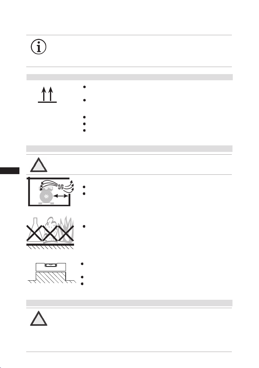
Setuponanevensurfaceorframewithsufcientload-
bearingcapacity.
Singlecompressorpreferablyonvibrationdamper.
Duplexandparallelcircuitsalwaysrigid.
Provideadequateclearanceformaintenancework.
Ensureadequatecompressorventilation.
Donotuseinacorrosive,dusty,dampatmosphereora
combustibleenvironment.
Fig.11
Fig.12
Fig.13
F
E
D
C
B
A
1
2
3
4
F
E
D
C
4
3
2
1
A
B
Tol.-Ang. DIN ISO 2768-mK
Ra Rz
Maß
Passung
Freigabe
Alternativbezug:
Baumustergeprüft
Teil inaktiv
Lieferantenzeichnung
-
-
K.-Auftrag:
PL:
Zeichnung ungültig
Entwicklungsstand
Teil keine Serie
120
400
±0.5
über 0.5
bis 6
Benzstraße 7 - 72636 Frickenhausen - Germany - www.bock.de
-
-
Unbemaßte Radien:
-
Diese Zeichnung ist unser Eigentum!
Sie darf ohne unsere Genehmigung weder nach-
gebildet, vervielfältigt, oder Dritten Personen zu-
gänglich gemacht werden. Der Nachbau nach
dieser Zeichnung, oder an Hand der nach dieser
Zeichnung hergestellten Gegenstände durch den
Abnehmer oder Dritte ist nicht gestattet.
Wir behalten uns alle Rechte, gemäß DIN ISO 16016
an dieser Zeichnung vor.
Bearb.
Datum
Änderungs-Nr.
Werkstoff:
Ausgangsteil, bzw. Rohteil:
--
Gepr.
Name
Datum
19.04.
Werkstückkanten
DIN ISO 13715
Ersatz für:
Ersetzt durch:
Erstellt
2010
Geprüft
-
Kurz
Zone
1/x
Oberflächenbehandlung / Härte:
-
Blatt:
Änderungsbeschreibung
400
Benennung:
±0.8
1000
30
6
-
±0.3
120
30
±0.2
Zeichn.-Nr. Teile-Nr.
Oberflächenangaben ISO 1302
x.xxxx-xxxxx.x
Zust.
Gußtoleranzen:
Gewicht: (kg)
±0.1
Maßstab:
1:1
Wasserwaage
für Indesign
Der Lieferant muß sicherstellen, dass die Ware in
einwandfreiem Zustand angeliefert wird (Korrosions-
schutz, Verpackung für sicheren Transport).
Rz 25
Rz 160
s
25
z
y
x
w
u
t
0,05
Rz 1,6
0,3
0,7
1,6
2
Rz 16
6,3
Rz 63
Rz 6,3
Rz 12,5
F:\user\kurz\3D Sachen\3D Teile\Zeichnungen\Wasserwaage
4.2 Setting up
?
4.1 Storage and transport
Usetransporteyelet.
Donotliftmanually!
Useliftinggear!
Storageat(-30°C)-(+70°C),maximumpermissiblerelativehumidity
10%-95%,nocondensation
Donotstoreinacorrosive,dusty,vaporousatmosphereorinacom-
bustibleenvironment.
Fig.10
Fig.9
INFO Newcompressorsarefactory-lledwithinertgas(3barnitrogen).
Leave this service charge in the compressor for as long as possible
and prevent the ingress of air. Check the compressor for transport
damage before starting any work.
ATTENTION Attachments (e.g. pipe holders, additional units, fastening parts,
etc.) directly to the compressor are not permissible!
ATTENTION Damage possible.
Do not solder as long as the compressor is under pressure.
Superheating can damage the valve. Remove the pipe supports
therefore from the valve for soldering and accordingly cool the
valve body during and after soldering.
Only solder using inert gas to inhibit oxidation products (scale).
4.3 Pipe connections
Dieses Handbuch passt für folgende Modelle
13
Inhaltsverzeichnis
Andere GEA Bock Luftkompressor Handbücher

GEA Bock
GEA Bock HA12P Bedienungsanleitung

GEA Bock
GEA Bock HGZ7 Series Bedienungsanleitung

GEA Bock
GEA Bock Bock HA5 Bedienungsanleitung

GEA Bock
GEA Bock In Touch HA4/310-4 Bedienungsanleitung

GEA Bock
GEA Bock EX-HG66e Series Bedienungsanleitung

GEA Bock
GEA Bock HGX44e CO2 Series Bedienungsanleitung

GEA Bock
GEA Bock HG34e A Series Bedienungsanleitung

GEA Bock
GEA Bock HG22e Series Bedienungsanleitung

GEA Bock
GEA Bock HA22e Bedienungsanleitung

GEA Bock
GEA Bock HG66e Series Bedienungsanleitung