
Gems GNSSRK-M-RDV Bedienungsanleitung

Page 2 / 20
Contents
1. System characteristics................................................................................................................................................................. 3
2. Installation diagram...................................................................................................................................................................... 4
3. Description ...................................................................................................................................................................................... 6
4. Typical Application........................................................................................................................................................................ 6
5. Equipment List With Standard Configuration .................................................................................................................... 6
6. System connection diagram ..................................................................................................................................................... 8
7. System Components..................................................................................................................................................................11
7.1 Digital Display Step Adjustable Amplifier RGA30-DV ........................................................................................11
7.1.1 Function:................................................................................................................................................................11
7.1.2 Specification.........................................................................................................................................................12
7.1.3 The amplifier Installation..................................................................................................................................12
7.2 Antenna...............................................................................................................................................................................14
7.2.1 Roof Antenna S440......................................................................................................................................14
7.2.2 GNSS antenna S440 installation ...................................................................................................................15
7.3 Re-radiate Antenna GRA10 .........................................................................................................................................17
7.4 Cable Assembly................................................................................................................................................................18
7.4.1 RG8 ..........................................................................................................................................................................18
7.4.2 XHY240 ..................................................................................................................................................................19
8 Typical faults and solutions.......................................................................................................................................................20
9 Frequency Reference Table.......................................................................................................................................................20

Page 3 / 20
1. System characteristics
GNSSRK Serial Repeater Kit
System signal:GPS/GLONASS/Beidou/Galileo/IRNSS/QZSS/SBAS/NAVIC/OmniStar
Frequency range of the antenna:1556~1623MHz and 1164~1288 MHz;
Frequency range of the amplifier:1164~1616 MHz;
Gain digital display adjustable in steps
Digital gain adjustment: 0-30dB, LED digital display;
Serial command control;
Input and output port power setting;
Coverage Range:
GNSSRK-M-RDV: A single antenna radiates a radius of 5-20
meters;
GNSSRK-M-RDV4: 4 antennas, each radiating 5-20 meters ;
GNSSRK-M-RDV8: 8 antennas, each radiating 5-20 meters;
The addition of the line amplifier GA40 to the front and end
of the system can extend the radiation range.

Page 4 / 20
2. Installation diagram
Satellite signals
l
Roof Antenna (S440)
(TIMING 4000)
Antenna (GRA10)
Step Adjustable Amplifier
XHY240, 10M
Lighting Protector
Indoor
GNSS Receiver
Satellite signals
RG8, 30M

Page 5 / 20
Installation steps
1. Receiving antenna S440 mounted on the roof;
2. Cable assembly RG8 fixed along the out wall, one terminator connects S440,the another to
protector at the appropriate place. In some special environment, select PE or PVC material
plastic pipe to protect the cable assembly is quite sensible;
3. Lightning arrester and amplifier fixed on the wall or on the table ;
4. Cable assembly XHY240 is fixed along the ceiling of the operating place;
5. Antenna GRA10 be fixed on the ceilling .
Quality Commitment
All products have been strictly inspected, all are qualified products.
We promise one-year guaranty and 5-year available.
Under warranty, products gone wrong which be identified not be human factor, can be
replaced free or repaired. Freight be charged by GEMS NAVIGAITON.
Return Policy
Our product and its packaging have LOGO and Serial-number, you should not tear up them,
as we will depend on them to deal with the return product.
Service phone:86-755-29644311 or email to: sales@gemsnav.com.

Page 6 / 20
3. Description
The GNSSRK-M-XXXX series GNSS repeater kit is to direct outdoor full-band navigation
satellite signals to places where indoor or other satellite signals cannot reach, and complete
various test work that should have been completed outdoors indoors.
4. Typical Application
For testing
For testing the cell- phone, PND, car navigators, tracker, survey products, etc.
For the purpose of GNSS signal covering
Car parks, lab, aviation manufacturing hangar, trade shows, Emergency-, safety
vehicles, public transportation etc.
5. Equipment List With Standard Configuration
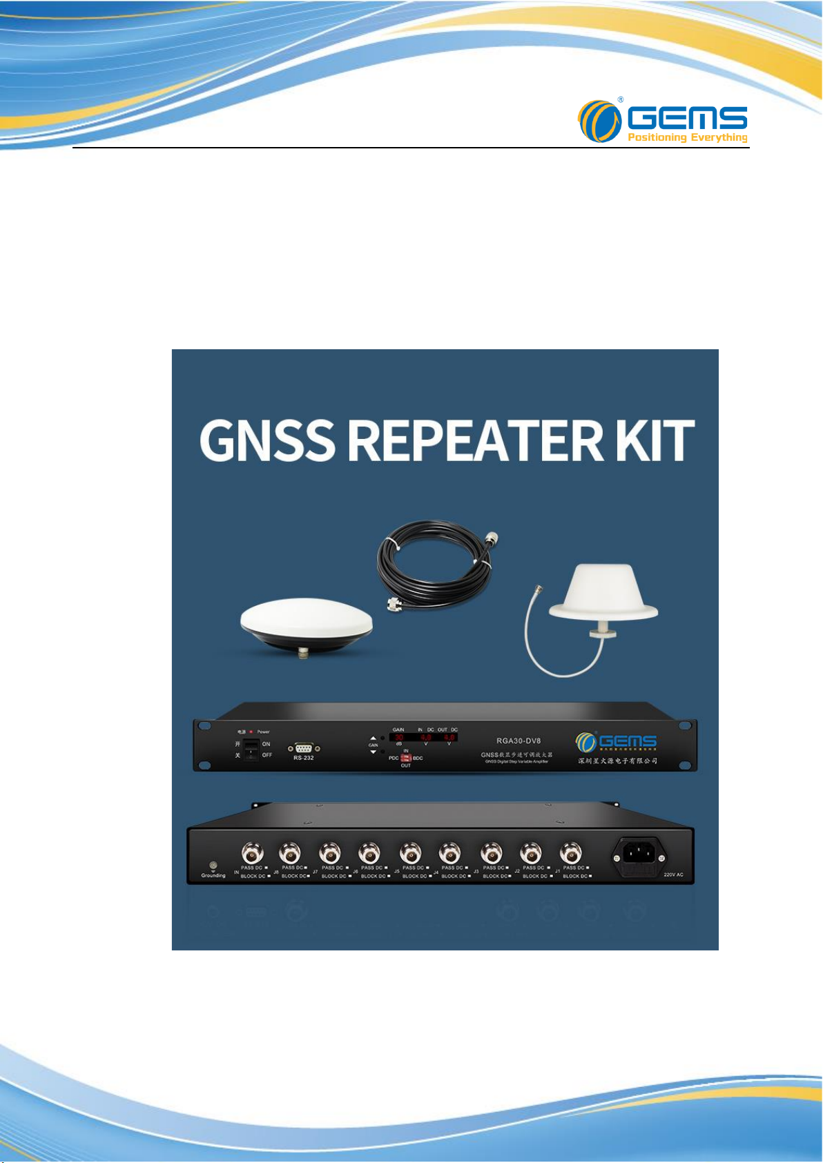
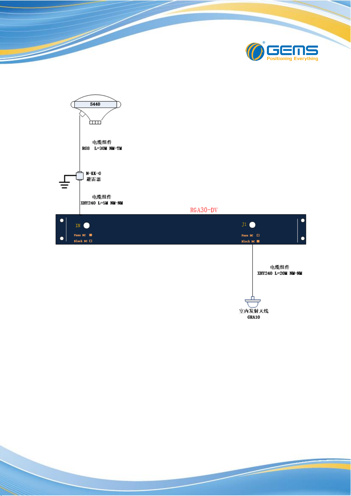
GNSSRK-M-RDV
Amplifier: RGA30-DV ,1 ea;
GNSS Antenna: S440,1 ea;
Cable Assembly: RG8,30M, 1ea;
Cable Assembly: XHY240,20M,1 ea;
Cable Assembly: XHY240,5M,1 ea;
Sending Antenna: GRA10,1 ea;
Ligting-protector: 1 ea;
Connector:NK-NK 1ea
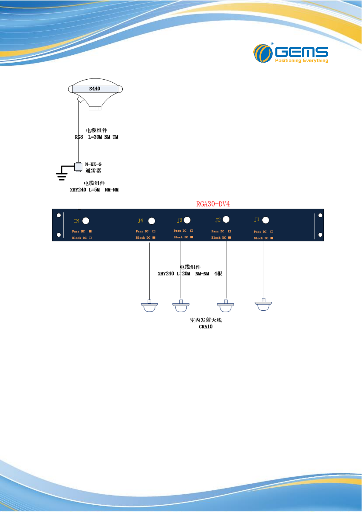
GNSSRK-M-RDV4
Amplifier: RGA30-DV ,1 ea;
GNSS Antenna: S440,1 ea;
Cable Assembly: RG8,30M, 1ea;
Cable Assembly: XHY240,20M,4 ea;
Cable Assembly: XHY240,5M,1 ea;
Sending Antenna: GRA10,4 ea;
Ligting-protector: 1 ea;
Connector:NK-NK 1ea

Page 7 / 20
GNSSRK-M-RDV8
Amplifier: RGA30-DV ,1 ea;
Receiving Antenna: S440,1 ea;
Cable Assembly: RG8,30M, 1ea;
Cable Assembly: XHY240,20M,8 ea;
Cable Assembly: XHY240,5M,1 ea;
Sending Antenna: GRA10,8 ea;
Ligting-protector: 1 ea;
Connector:NK-NK 1ea
RF coaxial cable assembly can make more choices according to the actual
needs of customers, please contact our company's sales for support.
Page 8 / 20
6. System connection diagram
GNSSRK-M-RDV
Page 9 / 20
GNSSRK-M-RDV4

Page 10 / 20
GNSSRK-M-RDV8
Dieses Handbuch passt für folgende Modelle
2
Inhaltsverzeichnis


