
General 50-755 MI Bedienungsanleitung
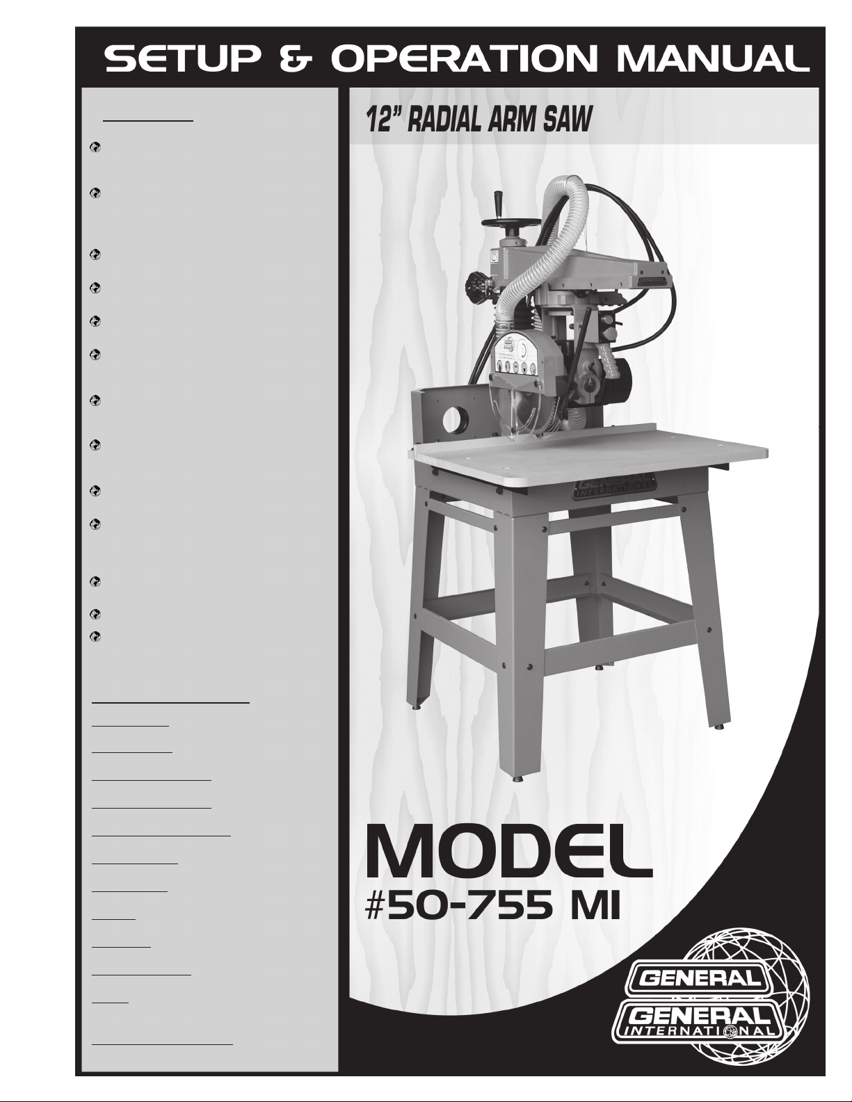
SPECIFICATIONS
BLADE DIAMETER
12” (305 mm)
ARBOR DIAMETER
5⁄8” (with 1” spacer bushing included)
MAX. DEPTH OF CUT AT 90°
3” (76 mm) w/12” blade, 2” (50 mm) w/10” blade.
MAX. DEPTH OF CUT AT 45°
2” (50 mm) w/12” blade
MAX. CROSSCUT W/ 12” BLADE
16” (407 mm) in 1” thick stock
MAX. RIP CAPACITY
26 3⁄8” (670 mm)
DADO CAPACITY
13⁄16” (21 mm)
TABLE SIZE
27 ½” x 35 3⁄8” (700 x 900 mm)
TABLE HEIGHT
36 ¾” (935 mm)
OVERALL DIMENSIONS
35 ¾” x 43 ¼” x 70 7⁄8” (900 x 1100 x 1800 mm)
MOTOR
M1: 2 HP, 220 V, 1 PH, 9.4 A
M2: 3 HP, 220 V, 3 PH, 9.5 A
SHIPPING WEIGHT / NET WEIGHT
580 lbs (263 kg) / 396 lbs (180 kg)
FEATURES
Cast-iron frame, heavy steel column and
sturdy easy to assemble all-steel stand
for perfect alignment and stability.
Industrial rated quality and versatile
design allows for standard crosscuts, as
well as bevels, miters, and head swivels
for rip cutting applications.
Precision adjustable indexing with posi-
tive stops at 90º, 45º and 22.5º.
Blade guard with anti-kickback safety
attachment and splitter.
Powerful 2 HP 220V single phase (M1) or
3 HP 220V 3-phase (M2) TEFC motor.
Magnetic switch with overload protec-
tion and a lock-out key to prevent unau-
thorized use of the saw.
Automatic mechanical safety brake
stops the blade in seconds upon shut-
down.
Dual 4” dust ports above the table, and
a 2” dust port on the rear of the blade
guard.
12” Negative rake, multi-purpose combi-
nation blade included.
Adjustable tension cutterhead/carriage
return spring to smoothly retract the
motor and carriage back to the start
position for extra safety.
5/8” arbor with 1” spacer bushing includ-
ed.
Replaceable steel guide ways.
Laser included.
VERSION 2_REVISION 2 - March 5, 2014
© Copyright General® International
THANK YOUfor choosing this General® International radial Saw. This
saw has been carefully tested and inspected before shipment and if properly used
and maintained, will provide you with years of reliable service. To ensure optimum
performance and trouble-free operation, and to get the most from your investment,
please take the time to read this manual before assembling, installing and operating
the unit. The manual’s purpose is to familiarize you with the safe operation, basic
function, and features of this saw as well as the set-up, maintenance and
identification of its parts and components. This manual is not intended as a
substitute for formal woodworking instruction, nor to offer the user instruction in the
craft of woodworking. If you are not sure about the safety of performing a certain
operation or procedure, do not proceed until you can confirm, from knowledgeable
and qualified sources, that it is safe to do so.
Once you’ve read through these instructions, keep this manual handy for future
reference.
GENERAL INTERNATIONAL
8360 Champ-d’Eau, Montréal (Québec) Canada H1P 1Y3
Téléphone (514) 326-1161 • Fax (514) 326-5555 • www.general.ca

RULESFORSAFEOPERATION
1. Do not operate the saw when tired, distracted, or under the effects of drugs, alcohol or any
medication that impairs reflexes or alertness.
2. The working area should be well lit, clean and free of debris.
3. Keep children and visitors at a safe distance when the saw is in operation; do not permit them to
operate the saw.
4. Childproof and tamper proof your shop and all machinery with locks, master electrical switches
and switch keys, to prevent unauthorized or unsupervised use.
5. Stay alert! Give your work your undivided attention. Even a momentary distraction can lead to
serious injury.
6. Fine particulate dust is a carcinogen that can be hazardous to health. Work in a well-ventilated
area and whenever possible use a dust collector and wear eye, ear and respiratory protection
devices.
7. Do not wear loose clothing, gloves, bracelets, necklaces or other jewelry while the saw is in
operation. Wear protective hair covering to contain long hair and wear non-slip footwear.
8. Be sure that adjusting wrenches, tools, drinks and other clutter are removed from the machine
and/or the feed table surface before operating.
9. Keep hands well away from the blade and all moving parts. Use a brush, not hands, to clear away
chips and dust.
10. Be sure that the blade is securely installed and in proper cutting direction before operation.
11. Be sure the blade has gained full operating speed before beginning to cut.
12. Always use a clean, properly sharpened blade. Dirty or dull blades are unsafe and can lead to
accidents.
13. If using a power feeder, stop the feeder before stopping the table saw.
14. Do not push or force stock into the blade. The saw will perform better and more safely when
working at the rate for which it was designed.
15. Use suitable support when cutting stock that does not have a flat surface. Always hold stock
firmly against the fence when ripping, or against the miter
gauge when cross-cutting.
16. To minimize risk of injury in the event of workpiece kickback, never stand directly in-line with the
blade or in the potential kickback path of the work piece.
17. Avoid working from awkward or off balance positions. Do not overreach while cutting; keep both
feet on floor. Never lean over or reach over the blade and never pull the work piece over the blade
from behind. Use out feed support or have an assistant
help when ripping long material.
18. Keep blade guards in place and in working order. If a guard must be removed for maintenance or
cleaning, be sure it is properly reattached before using the tool again.
19. Never leave the machine running with the power on when not in operation.

20. Use of parts and accessories NOT recommended by GENERAL INTERNATIONAL may result in
equipment malfunction or risk of injury.
21. Never stand on machinery. Serious injury could result if the tool is tipped over or if the blade is
unintentionally contacted.
22. Always disconnect tool from power before servicing or changing accessories such as blades, or
before performing any maintenance, cleaning or adjustments, or if the machine will be left
unattended.
23. Make sure that switch is in "OFF" position before plugging in the power cord.
24. Make sure the tool is properly grounded. If equipped with a 3-prong plug it should be used with a
three-pole receptacle. Never remove the third prong.
25. Do not use this saw for other than its intended use. If used for other purposes, GENERALR
INTERNATIONAL disclaims any real implied warranty and holds itself harmless for any injury, which
may result from that use.
5

UNPACKING AND CLEANING
Carefully unpack the machine and all loose items from the shipping container(s). Remove the
protective coating from all unpainted surfaces. This coating may be removed with a soft cloth
moistened with kerosene (do not use acetone, gasoline or lacquer thinner for this purpose). After
cleaning, cover the unpainted surfaces with a good quality household floor paste wax.
To reduce the risk of injury, do not connect the machine to the power source until the
machine is completely assembled and you read and understand the entire instruction
manual.
A. MACHINE (NOT SHOW)
B. 12” BLADE
C. LEG BRACE SHORT
D. LEGS
E. LEG BRACE
F. SPREADER
G. 2” HOSE
H. HARDWARE BAG
C
D
E
F
G
H
B
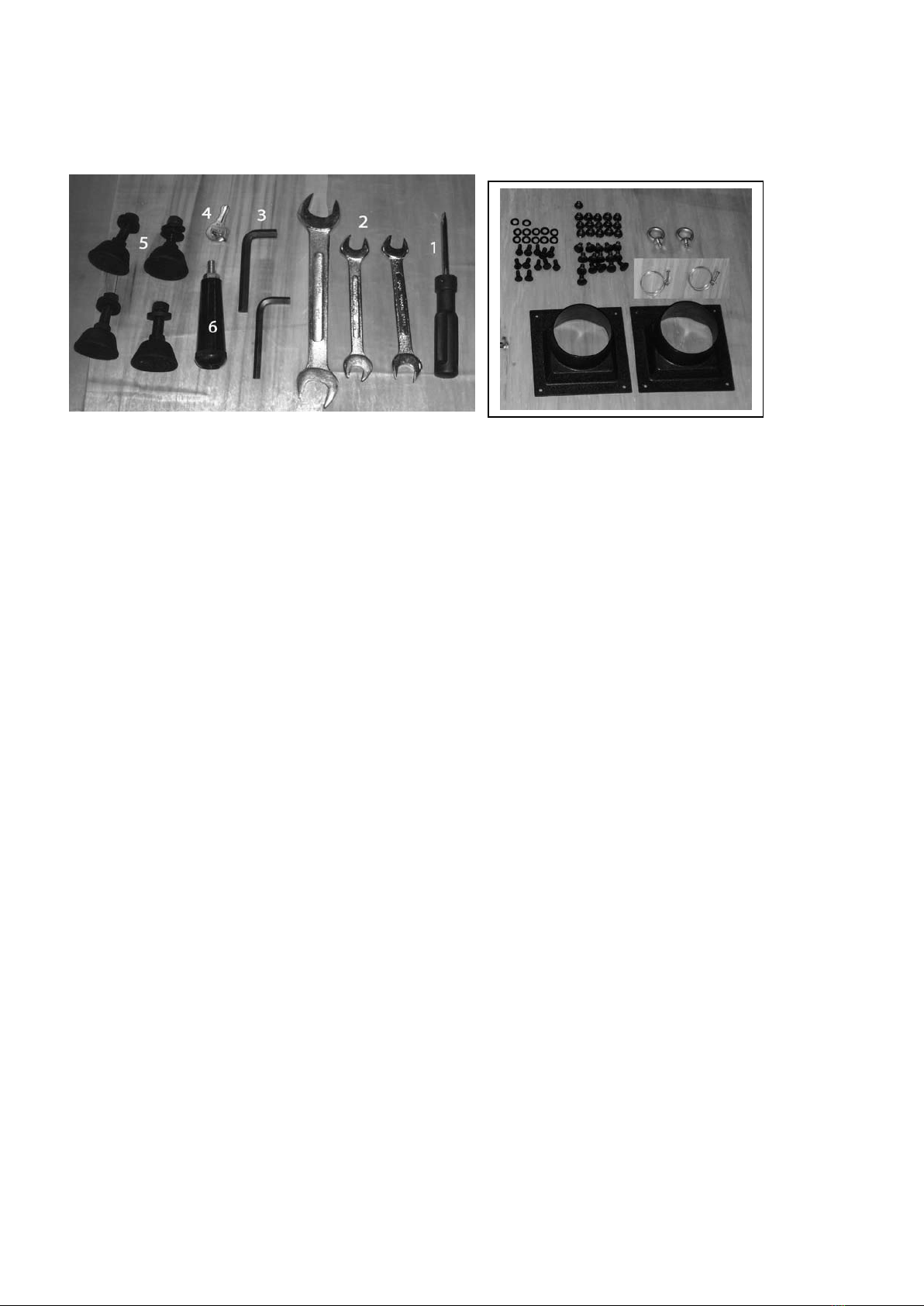
HARDWARE BAG
1. SCREW DRIVER 1 PCS
2. WRENCH 11/13,12/14,21/23 3PCS
3. ALLEN KEY 2PCS
4. KEY FOR SWITCH 1PCS
5. FOOT PAD WASHERS AND SCREWS 4PCS
6. KNOB 1PCS
7. SCREWS 12PCS
WASHERS 12PCS
8. SCREWS 16PCS
WASHERS 18PCS
9. HOSE CLAMP 2”2PCS
10.HANGER 2PCS
11.DUST CHUTE 2PCS
7
8
9
8 10
11
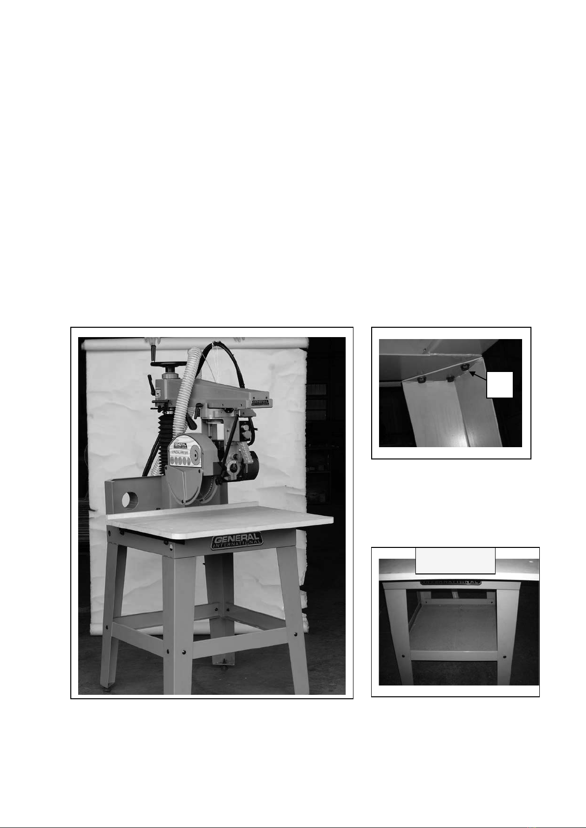
ATTACHING STAND TO THE MACHINE
1. Assemble the stand first. with 16 shoulder bolts, washers and hex nuts, begin assembling one
end of stand by attaching 1 short shelf and 1 long brace to legs
2. Assemble the opposite side of the stand the same way as described in step 1.Then use the 2
short shelves and 2 long braces to join both assembled ends and complete the stand then upside
down complete stand in leveling place tighten all nuts.
3. Attach the 4 leveling feet to the stand by using 4 hex nut and 8 washers, place in its final location
after fully assembly, level the feet by loosening top nut, adjusting lower nut up or down on the
screw stem as needed, then tightening down the top nut
4. Use a heavy-duty lifting device (fork lift, pulley, etc.) with lifting straps and steel rods that can
support the weight to lift the machine to stand, assemble the stand to each corner (see picture) of
the baseunderneath. Use 12 hex head screws & flat washers (B)
*If you needed tool storage, please measure the length and width of
braces, and cut the thickness as you required for the wood piece. Put the
wood piece onto stand braces for tool tray.
OPTIONAL
B

ATTACHING THE OVERARM ELEVATING HAND WHEEL
1. Fasten the elevating handle wheel knob to the elevating wheel(A).
2. Adjust cable hanger to “B” position.
3. Remove the screws located on back side of dust bracket ,assemble the dust chute to dust
bracket(C).
4. Remove the screws located on back side of base, and then assemble the switch box to
the base(D).
5. Assemble the hose to dust bracket tighten hose clamp(E).
BA
C
D
E
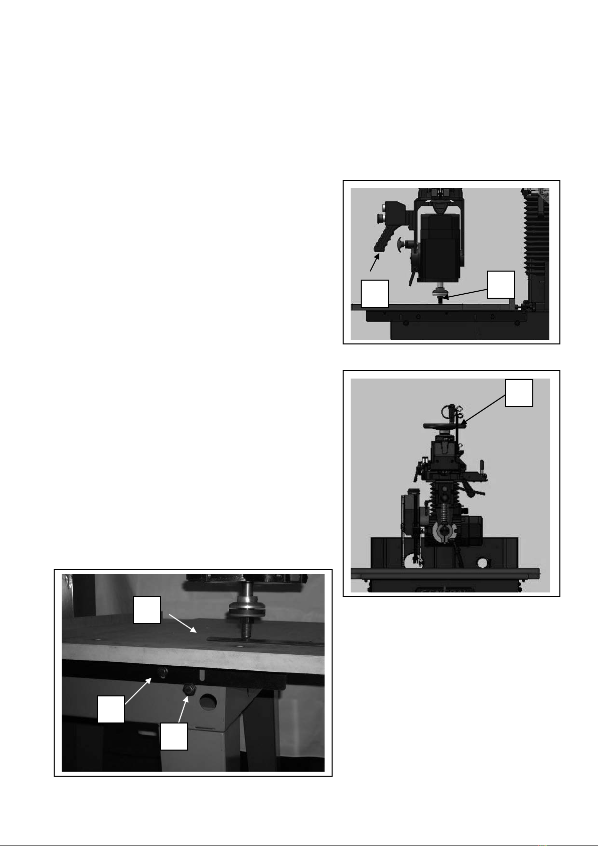
ADJUSTING TABLE TOP
PARALLEL TO TRACK-ARM
For accurate work the track-arm must be parallel to
the table top at all points. To check and adjust:
1. Move the motor and cutterhead assembly to
the vertical position . Position saw arbor (A), so that it
is approximately in the center of the front table board.
Pull track-arm clamp handle (B) to the rear to secure
track-arm and tighten cutterhead clamp knob. Using
the block (C) as a feeler gauge, raise or lower
track-arm by turning elevating handle (D) until saw
arbor (B) just touches block (C). DO NOT RAISE OR
LOWER TRACK-ARM ANY FURTHER UNTIL
LEVELING ADJUSTMENT IS COMPLETED.
2. Move cutterhead until the saw arbor (A) is at the left
front table, as shown. Make sure track-arm clamp
lever and cutterhead lock knob are tightly. Using the
block (C) as a feeler gauge check to see if an
adjustment is necessary. To lower the table, loosen
nut (E) and adjust screw (F) to raise the table, reverse
this adjustment. Check table back at points and adjust
if necessary. Check table on right side in the same
manner.
A
B
C
D
E
F

BLADE GUARD AND ANTIKICKBACK DEVICE
1. Remove the outer blade guard.
2. Remove arbor nut and outer blade flange .
3. Install blade on the saw arbor with teeth of blade pointing downward when viewed from
front of saw, and thread the arbor nut onto the arbor.
4.IMPORTANT: To prevent arbor nut from spinning when blade stops, place the Allen
key into the shaft hole and firmly tighten arbor nut with the 21mm spanner wrench
(left handed thread).
5. Place outer blade guard in place and fasten cap screws.
7. Assemble spreader to blade guard, and fasten in place with cap screws.
NOTE: It will be necessary to tighten the blade guard and anti-kickback rod.
Inhaltsverzeichnis
Andere General Gesehen Handbücher

General
General 90-040 Stücklistenhandbuch

General
General 90-170B M1 Stücklistenhandbuch

General
General F-36 T-28 Bedienungsanleitung

General
General 90-140 SM1 Stücklistenhandbuch

General
General 350 MI Stücklistenhandbuch

General
General 90-270 Stücklistenhandbuch

General
General 90-050 Stücklistenhandbuch

General
General 90-725 Bedienungsanleitung

General
General Excalibur EX-16CE Stücklistenhandbuch

General
General 90-200 M1 Stücklistenhandbuch


