Giant MPH-3 - MODEL YEAR 2002 Bedienungsanleitung

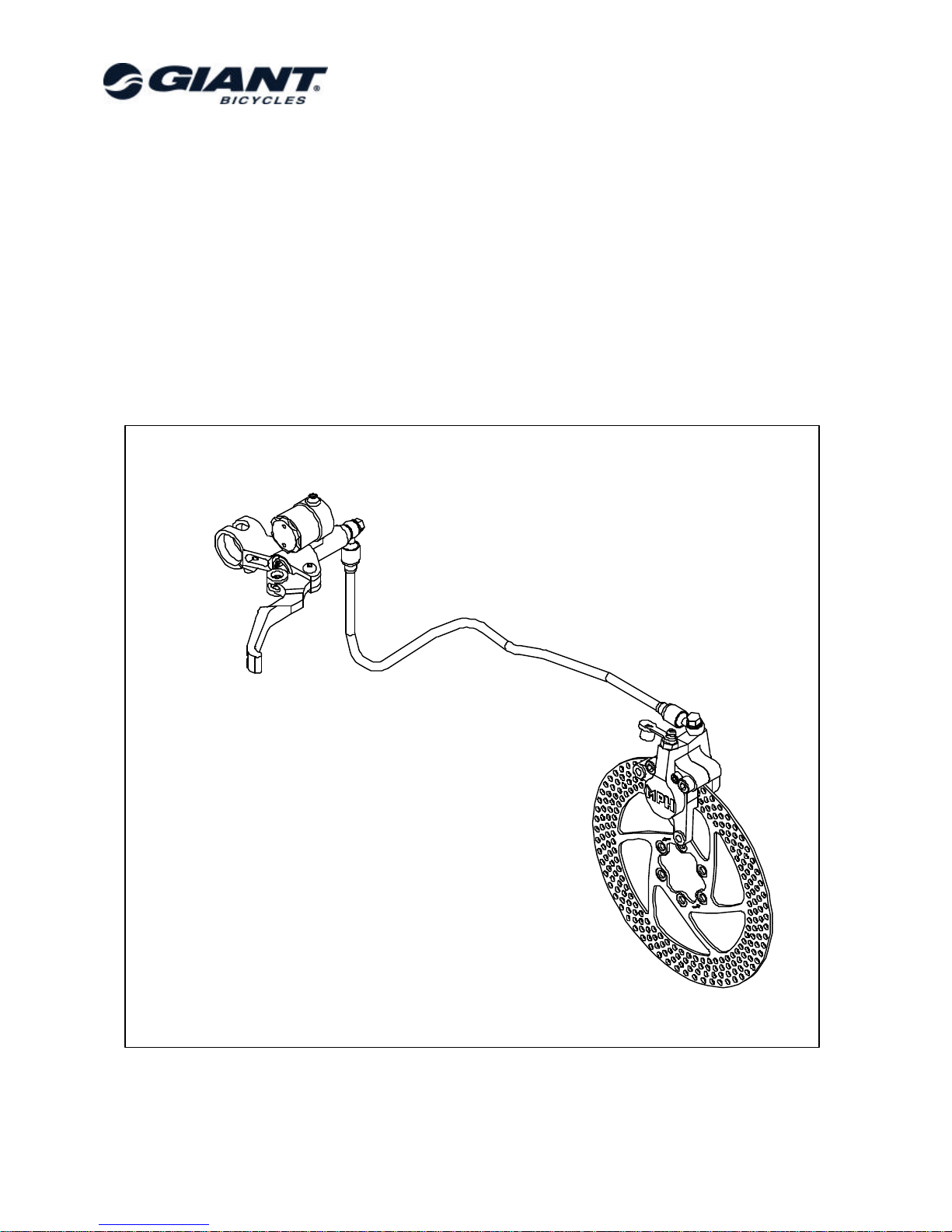
Giant MPH-3
Disc Brake System
Model Year 2002
Owners Manual
June 2001.
•
Fixation calipers and rotors: International Standard
•Fully hydraulic disc brake system
•2 piston closed system
•Brake levers with reach adjusters
•Pressure point & brake pad clearance adjustable
“on the fly”
•Easy brake pad replacement
•Standard “DOT 4 or DOT 5.1” brake fluid

-Pag. 2. -
Contents:
1. Warnings 3
2. Mounting the brake system on the bicycle 4
2.1 Assembly of rotor 4
2.2 Assembly of brake lever 5
2.3 Assembly of hose 6
2.4 Assembly of caliper “Post Mount” (Manitou forks) 7
2.5 Assembly of caliper “International Standard” 8
3. Adjustment 9
3.1 Pad clearance adjustment 9
3.2 Lever reach adjustment 10
3.3 Angle of the brake fluid reservoir 10
4. Tightening torque 11
5. Maintenance 12
5.1 General 12
5.2 Replacement of brake pads 14
5.3 Bleeding procedure 15
6. Trouble shooting and -prevention 20

-Pag. 3. -
1. Warnings
Please read this owners manual carefully.
Improper assembly of the wheels or malfunction of the brake
system may be extremely hazardous and could cause accidents,
even fatal ones. Be sure to learn the proper braking technique
and operation of your bicycle.
Consult your professional bicycle dealer and this owners manual
for this.
Giant recommends not using this system for any downhill
competition.
It is particularly suited for cross country use.
Giant advises to have your wheels laced by an expert mechanic.
Improper tightening of the spoke nipples or thin spokes may
result in deformation of the wheel and can cause serious
accidents.
Protect vital parts of the bike from spilling brake fluid by holding a
rag around the brake fluid reservoir, and use protective gloves
and safety goggles when working with brake fluid.
Brake fluid spillage (for instance on the rotor) can cause
contamination of the brake pads.

-Pag. 4. -
2. Mounting the brake system on the bicycle
2.1 Assembly of rotor
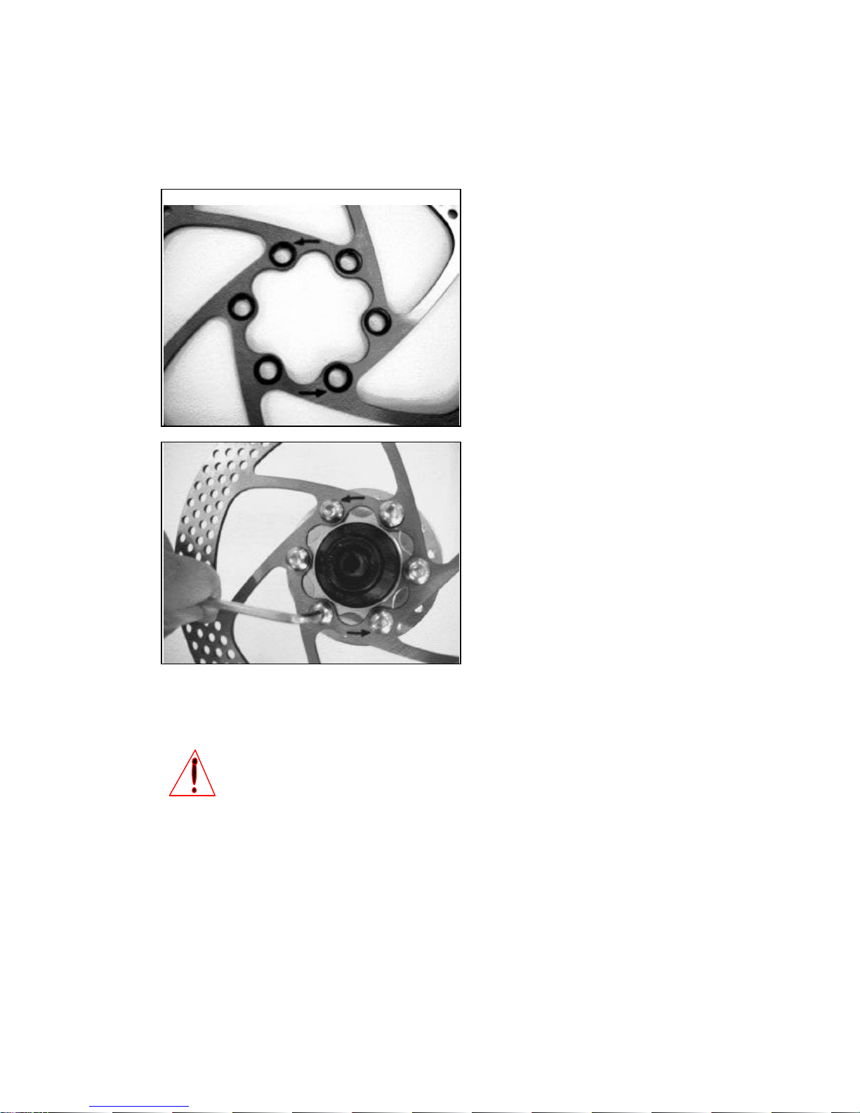
Place the rotor on the hub flange taking care that
the arrows on the internal part of the rotor are
pointing in the direction of rotation of the wheel.
Mount the rotor with the six M5 bolts onto the hub
with a T25 Torx key to a torque of 4 Nm.
Tighten the bolts in a crossed pattern.
Threads of new bolts have been coated with blue
material that prevents that bolts come loose.
Always use LoctiteTM Primer (#7649) and
LoctiteTM blue Removable Threadlock (#242) or
similar material on thread of these bolts during
re-assembly.
Then install the wheel into the frame / front fork
with the rotor at the left hand side and fix the
wheel in the dropouts.
Warning!
It is essential that the disc is clean (free from grease or oil residues) to avoid contaminating
the brake pads and to insure perfect braking.
Grease can be removed from the rotors with a citrus based cleaner.

-Pag. 5. -
2.2 Assembly of brake lever
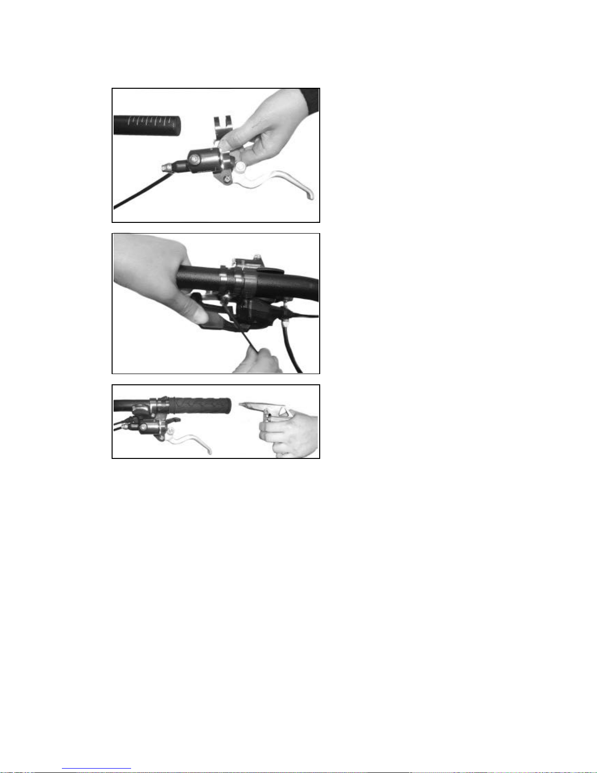
Place a complete brake lever assembly onto the
handlebar.
Set the brake lever to the right position.
Tighten the fixing bolt with a 4 mm. Allen-key.
Recommended tightening torque: 6 Nm.
Blow compressed air into the grip through a small
hole at the end and slide the grip over the
handlebar.

-Pag. 6. -
2.3 Assembly of hose
Length and attachment of hoses:
The hoses have to be attached to the frame and fork so that they do not contact the wheel or tire, or
interfere with the travel of the suspension or the action of steering. Use the bike’s cable guides and zip
ties to attach the hoses. Also be sure that the hose is not so long as to possibly snag on anything while
riding.
A hose that is too short may cause steering problems but can also cause strain on the hose which may
result in the hose getting disconnected from the caliper of brake lever.
For maximum efficiency of the system, it is very important that the hoses are without kinks and have the
correct length.
Changing the length of a hose should be done by an authorised Giant dealer.
After assembling the brake lever, put the
caliper (front brake) from the front side to the
backside through the opening between left
hand fork leg and front wheel and fix the
caliper to the dropout
(see: “assembly of caliper”).
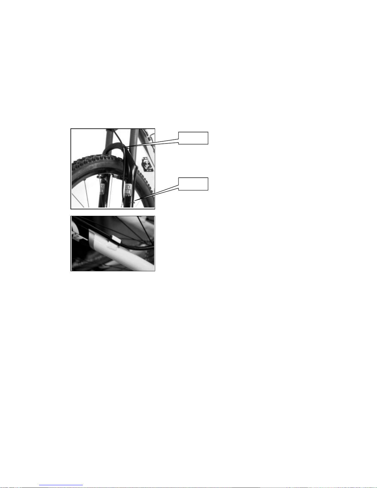
Fix the hose of the front brake to the front
fork.
Use zip-ties or other parts to fix the hose to
the fork brace and the lower fork leg
(left hand side).
Fix the hose of the rear brake to the frame.
Push the hose into the hose guides on the
top tube and the left hand seat stay.
Zip-tie
Zip-tie

-Pag. 7. -
2.4 Assembly of caliper “Post Mount” (Manitou forks)
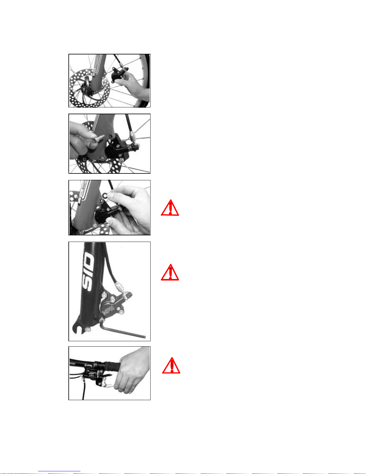
1. Assemble the front brake caliper to the Giant postmount adapter
(see picture) and use a 5 mm. Allen-key to tighten the two M6
fixing bolts.
Notes:
- the lower bolt for the front caliper is shorter !
- watch the orientation of the “GIANT” logo !
- recommended tightening torque: 9 Nm.
2. Hold the postmount adapter with the front caliper close to the disc
brake mount on the front fork / frame, with the rotor placed
between the brake pads.
Screw in the two M6 fixing bolts, but don’t tighten them.
The postmount adapter should be able to move.
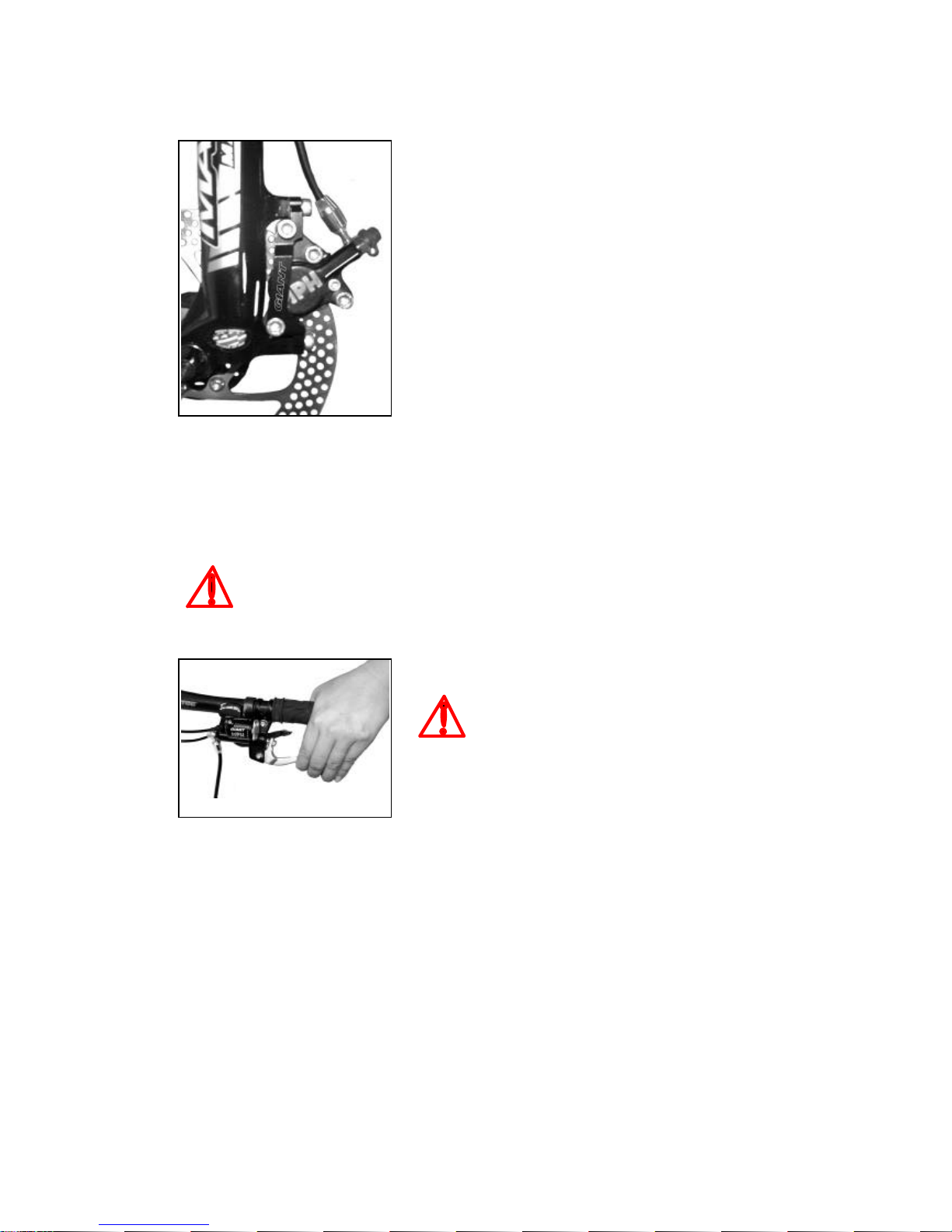
3. Now squeeze the brake lever, so the rotor is clamped by the
caliper.
Use a 5 mm. Allen-key to tighten the M6 fixing bolts.
Recommended tightening torque: 9 Nm.
4. Now you can release the brake lever.
Pull the brake lever to see if the brake pads are actuated well.
If the procedure has been followed well, the caliper (and brake
pads) is set parallel to the rotor and the rotor is exactly in middle of
the brake pads.
If necessary, release the bolts that fix the postmount adapter to the
front fork.
Repeat the whole procedure mentioned above or just move the
postmount adapter a bit.
Don’t forget to tighten the fixing bolts again.
Threads of new bolts have been coated with blue material that prevents that bolts come
loose.
Always use LoctiteTM Primer (#7649) and LoctiteTM blue Removable Threadlock (#242)
or similar material on thread of these bolts during re-assembly.
Make sure that the brake pads are well
centered and balanced.

-Pag. 8. -
2.5 Assembly of caliper “International Standard”
Hold the caliper close to the disc brake mount on the front fork /
frame, with the rotor placed between the brake pads.
Screw in the two M6 fixing bolts, but just a few threads.
Note: the lower bolt for the front caliper is shorter!
Now squeeze the brake lever, so the rotor is clamped by the
caliper.
The space between the caliper and the disc mount has to be filled
up with washers.
Make an estimation how big the gap is, so, how many washers are
needed. Try !
For both the upper and the lower caliper fixing bolts.
Example:
If the gap is approx. 1 mm., you may need 4 washers of 0.25 mm.
thickness.
Put the washers between the frame/fork mount and the caliper.
Use a 5 mm. Allen-key to tighten the M6 fixing bolts.
Note: the lower bolt for the front caliper is shorter!
Pull the brake lever to see if the brake pads are actuated well.
If the procedure has been followed well, the caliper (and brake
pads) is set parallel to the rotor and the rotor is exactly in middle of
the brake pads.
If necessary, release the bolts that fix the brake caliper to the fork
and remove or add washers.
Don’t forget to tighten the fixing bolts again.
Use washers of 0.25 or 0.5 mm. thickness for each bolt
to set the caliper (brake pads) parallel to the rotor and
to set the rotor exactly in middle of the brake pads.
Threads of new bolts have been coated with blue
material that prevents that bolts come loose.
Always use LoctiteTM Primer (#7649) and LoctiteTM blue
Removable Threadlock (#242) or similar material on
thread of these bolts during
re-assembly.
Recommended tightening torque: 9 Nm.
Make sure that the brake pads are well centered and
balanced.

-Pag. 9. -
3. Adjustment
3.1 Pad clearance adjustment
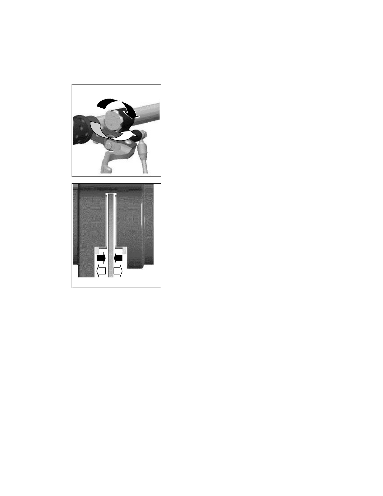
Turn the adjust knob of the brake lever’s brake fluid reservoir and
pull the brake lever until you have found the best braking position
for your hand
(to set the pressure point of the braking system to personal
preference).
Turning inwards (clockwise):
distance between the brake pads becomes smaller, so, smaller
brake lever stroke required.
Turning outwards (anti-clockwise):
distance between the brake pads becomes bigger, so, bigger
brake lever stroke required.
Due to normal pad wear during riding, the clearance between the
padsand rotor will increase.
So, it’s important to check the adjustment before and during each
ride.
Brake pad wear can be compensated and brake pad to rotor
clearance can be adjusted.
Turn the adjust knob clockwise to bring the brake pads closer to
the rotor.
(Illustration: caliper, brake pads and rotor).
If you’re not able to adjust the brake system to the desired braking point (position of your hand or brake
lever blade when the brake pads engage the rotor), please check if the pads are worn out.
If so, replace place them.
If no, please consult your authorised Giant dealer.

-Pag. 10. -
3.2 Lever reach adjustment
Find out the best lever reach by using a
2.5 mm.Allen-key to adjust the screw as shown in
the illustration.
For big hands:
turn clockwise / inwards to increase the distance
between the handlebar and the lever blade.
For small hands:
turn anti-clockwise / outwards to reduce the
distance between the handlebar and the lever
blade.
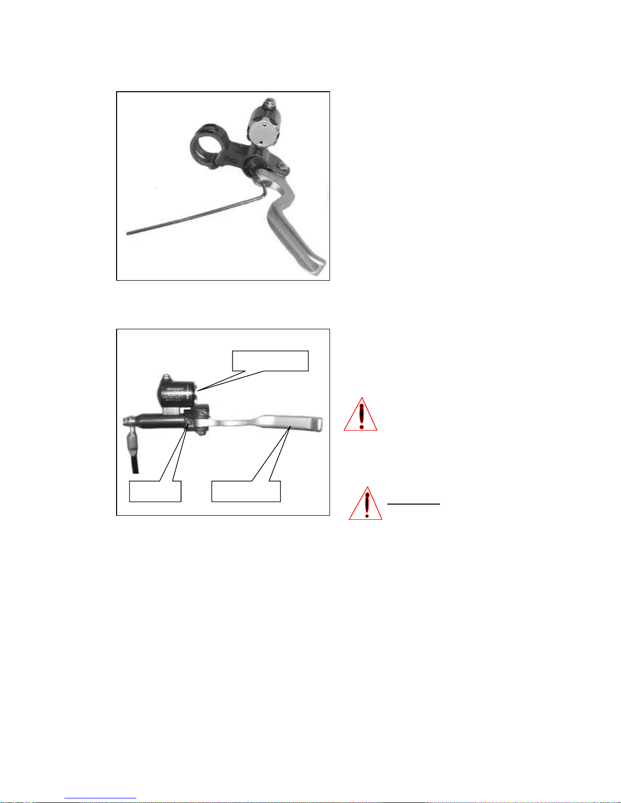
3.3 Angle of the brake fluid reservoir
The function of the small screw (see picture) close
to the lever blade is setting the angle of the
master cylinder.
Use a 2 mm. Allen-key to loosen the screw and
adjust the angle of the master cylinder.
Note:
Make sure that it’s possible to turn the
adjust knob. If the adjuster touches the
lever bracket (clamp), turning may be
impossible !
After this, tighten the screw again.
Note:
Not too tight: Otherwise the master
cylinder will be deformed. Tighten the
screw just enough to fix the master
cylinder.
Screw Lever blade
Adjust knob
Inhaltsverzeichnis
Beliebte Motorradzubehör Handbücher anderer Marken

SRC
SRC B-TRK502-01-01-SL Bedienungsanleitung

3M
3M Speedglas 9100 MP Bedienungsanleitung

hepco & becker
hepco & becker 6307520 00 01 Bedienungsanleitung

HOMCOM
HOMCOM AA0-077 Bedienungsanleitung

hepco & becker
hepco & becker 6307558 00 01 Bedienungsanleitung

Wunderkind Custom
Wunderkind Custom 106503-F15 Benutzerhandbuch