Growatt GroBoost Bedienungsanleitung

SHENZHEN GROWATT NEW ENERGY TECHNOLOGY CO.,LTD
GroBoost quick installation guide

Catalog
一、Overview..................................................................................................... 1
二、Installation................................................................................................... 6
三、Multiple Work Modes................................................................................. 11
四、Device parameters.................................................................................... 21
五、Common Problem..................................................................................... 22
六、APP Register ............................................................................................ 23
七、GroBoost Setting the Groboost via Shinephone APP................................ 25

1
一、Overview
◆Package List
Open the package, take out all the accessories, and check the quantity of all
the components in the box according to the package list, As shown in Figure
1-1 and Table 1-1.
Figure 1-1
Cod
e
Accessories
Number
A
GroBoost whole machine
1
B
PT1000 temperature sensor
1
C
Antenna
1
D
Quick installation guide
1
E
Wall-mounted bracket Screws
3
F
Seal bottom cover screw
4+2(More than)
G
3 PIN large load terminal
4
H
5 PIN AC input large terminal
1

2
I
6 PIN PT1000 small terminal
1
J
3 Pin RS485 and 12VDC small terminal block
2
Table 1-1
◆Product description
ShineLink adopts a device-gateway-server-client architecture model, which
uses gateways and servers to link household energy equipment with
homeowners to realize the entire function of monitoring, analysis, and
scheduling. Among them, GroBoost could control the temperature of the water
heater, and work automatically when the solar system has surplus power
exporting to the grid to maximize solar self-consumption.
Figure 1-2
GroBoost is a power regulator to adjust its power output automatically
based on resistive loads through wireless commands. With the ShineLink
system, it communicates with ShineLanBox through RF signal, accepts
commands to adjust power output, and realizes system energy distribution and
scheduling. The diagram of one of its application scenario is shown in Figure

3
1-2, in which the Inverter is communicated with the meter through RS485, and
communicate with the LanBox through ShineRFStick.
This application scenario is suitable for the Growatt new generation
inverter, like MIN, MID, MOD, SPH and SPA series, which could support to
upload the energy meter date to the server.
Figure 1-3
The diagram of another application scenario is shown in Figure 1-3, the smart
meter data is transmitted wirelessly to the LanBox through RailLog, which is
suitable for the -s series inverter which can’t upload the energy meter data to
the server.
◆ GroBoost Interface
As shown in Figure 1-4, the device has four indicator lights, four function
buttons and three waterproof connector, corresponding to different wiring input.
The functions and definitions are shown in Table 1-2.

4
Figure 1-4
No
Description
No
Name
Description
A
Indicator lights
1
LED1
Indicator lights for phase
L1
B
Buttons
2
LED2
Indicator lights for phase
L2
C
电源线接线头
3
LED3
Indicator lights for phase
L3,and for the RF
communication status
D
负载线接线头
4
LED4
Power indicator
E
信号线接线头
5
L1
Phase L1 control button
6
L2
Phase L2 control button

5
7
L3
Phase L3 control button
8
Home
RF pairing / Reset /
Factory Reset
Table 1-2
The following figure 1-5 is the wiring interface of GroBoost, and its functions and
definitions are detailed in Table 1-3.
Figure 1-5
NO
Description
NO
Description
1
Relay A input port
13
Input PE earth wire
2
Relay B output port
14
Input N zero line
3
Relay C output port
15
Enter L1 FireWire
4
TP1000—L1
16
Enter L2 FireWire
5
TP1000—L2
17
Enter L3 FireWire
6
TP1000—L3
18
Output PE earth wire
7
12V DC-DC
19
Output N zero line
8
12V DC-DC
20
Output L3 FireWire
9
GND (12V DC)
21
Output PE earth wire
10
RS485+ (D+)
22
Output N zero line
11
EARTH
23
Output L2 live wire

6
12
RS485- (D-)
24
Output PE earth wire
25
Output N zero line
26
Output L1 live wire
Table 1-3
二、Installation
Notice:
⚫Make sure to read the instructions to understand product information and
safety precautions before installation;
⚫The installer must use insulated tools and wear safety equipment during
the installation procedure;
⚫Construct sun and rain shelters to avoid GroBoost directly exposed to
sunlight and rain.
Figure 2-1
◆Installation Process
⚫Fix the wall-mounted bracket hanging on the wall with screws, drill holes in
the wall after positioning the four screw holes, put the plastic expansion

7
tube, and screw into the wall, to fix the wall hanging.
Figure 2-2
⚫There are four screws on the bottom cover of the whole machine,
please use a screwdriver to dismantle the screws.
Figure 2-3
⚫Remove the lower cover and start to wire it.
Figure 2-4
Loosen these screws
8
⚫The wire harness passes through the corresponding three terminals and
screwed themon the terminals. A 5 pin three-phase power input terminal is
for power input line, 3 pin power output terminals is for loads, and the 3 pin
RS485 and 12Vdc terminals are for the communication of the future
application.
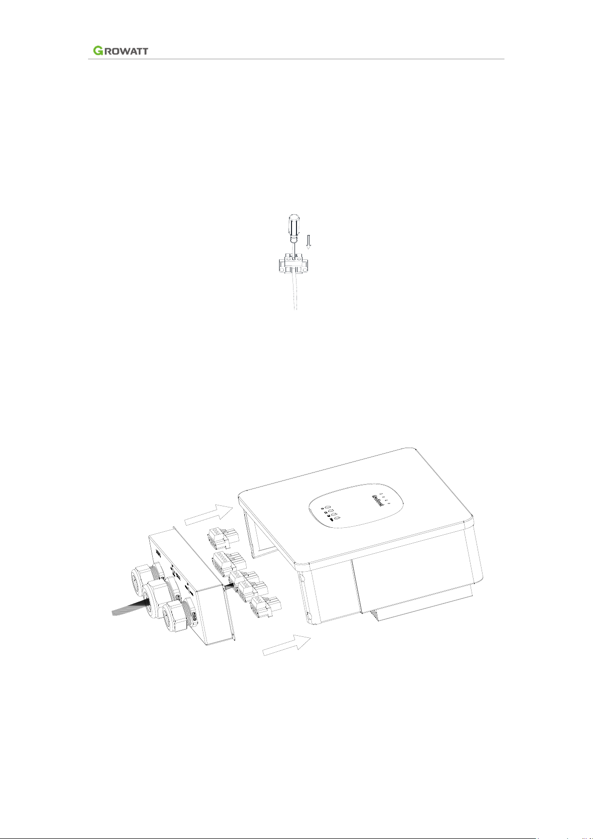
Figure 2-5
⚫Screw the wire on the male terminal, connect it to the corresponding
female socket of the device, and fix screws on both sides of the terminal to
fix the terminals.
Figure 2-6
⚫Adjust wiring distance and screw the four screws fixing the sealing lower
cover to fix the lower cover.
Inhaltsverzeichnis


