
Hamworthy TYNEHAM AHP60 Benutzerhandbuch

IMPORTANT NOTE
THESE INSTRUCTIONS MUST BE READ
AND UNDERSTOOD BEFORE INSTALLING,
COMMISSIONING, OPERATING OR
SERVICING EQUIPMENT
INSTALLATION, COMMISSIONING AND
SERVICING INSTRUCTIONS
Air/water monobloc
heat pump
TYNEHAM AHP60
Models: 50 and 70 kW

Technical Enquiries
To supplement the detailed technical brochures, technical advice on the application and use of products in the Hamworthy
Heating range is available from our technical team in Poole and our accredited agents.
Site Assembly
Hamworthy oer a service of site assembly for many of our products in instances where plant room area is restricted.
Using our trained sta we oer a higher quality of build and assurance of a boiler built and tested by the manufacturer.
Commissioning
Commissioning of equipment by our own engineers, accredited agents or specialist sub-contractors will ensure the
equipment is operating safely and eciently.
Maintenance Agreements
Regular routine servicing of equipment by Hamworthy service engineers inspects the safety and integrity of the plant,
reducing the risk of failure and improving performance and eciency. Maintenance agreements enable our customers to
plan and budget more eciently.
Breakdown service, repair, replacement
Hamworthy provide a rapid response breakdown, repair or replacement service through head oce at Poole and
accredited agents throughout the UK.
Spare Parts
A comprehensive spare parts service is operated from our factory in Poole, providing replacement parts for both current
and discontinued products. Delivery of parts and components is normally from stock within seven days. However, a next
day delivery service is available for breakdowns and emergencies.
Telephone: 0845 450 2866 E-mail: [email protected] Fax: 01202 662522
Customer After Sales Services

01.07.2022 3 / 78
AHP60-50/70 - Installation, Use and Maintenance
CONTENTS
1.
REGULATIONS, RECOMMENDATIONS AND WARNINGS..............................................................5
1.1. Applicable regulations and standards ........................................................................................................... 5
1.2. Recommendations and warnings................................................................................................................. 5
2. DESCRIPTION OF THE EQUIPMENT ..............................................................................15
2.1. Designations and scope.............................................................................................................................. 15
2.2. Packaging ................................................................................................................................................... 15
2.3. Denitions ................................................................................................................................................... 15
2.4. Technical data ............................................................................................................................................. 16
2.5. Description .................................................................................................................................................. 20
2.6. Operating principle ...................................................................................................................................... 22
3. INSTALLATION ...................................................................................................................24
3.1. Lifting and handling ..................................................................................................................................... 24
3.2. Installation ................................................................................................................................................... 25
3.3. Installing the outdoor unit ............................................................................................................................ 25
3.4. Installing the control unit ............................................................................................................................. 32
3.5. Position of the centre of gravity and the vibration shock absorbers............................................................ 32
3.6. Hydraulic connections ................................................................................................................................. 33
3.7. Electrical connections ................................................................................................................................. 39
4. PRE-REQUISITES BEFORE COMMISSIONING .............................................................44
4.1. Verication before switching on................................................................................................................... 44
4.2. Switching On ............................................................................................................................................... 45
4.3. Commissioning ........................................................................................................................................... 45
4.4. Primary loop ow rate/cascade balance adjustment................................................................................... 45
4.5. Operating
diagram ....................................................................................................................................... 46
4.6. TYNEHAM user interface navigation .......................................................................................................... 48
5. CONTROL INTERFACE .....................................................................................................49
5.1. User interface.............................................................................................................................................. 49
5.2. “SET” setpoint menu (For manual operation only) ................................................................50
5.3. Sensor menu [TP] ....................................................................................................................................... 51
5.4. Error menu [Err] .......................................................................................................................................... 51
5.5. Operating hours menu [OHR] ..................................................................................................................... 51
5.6. Parameter menu [Par]................................................................................................................................. 51
6. TROUBLESHOOTING .......................................................................................................52
6.1. Troubleshooting of failures without error code ............................................................................................ 52
6.2. Error codes and diagnostic assistance ....................................................................................................... 52
6.3. Inverter board errors ................................................................................................................................... 59
6.4. Ohmic values of the various sensors .......................................................................................................... 61
7. MAINTENANCE OF THE OUTDOOR UNIT......................................................................62
7.1. Drainage of the outdoor unit on the water side ........................................................................................... 62
7.2. Filling the outdoor unit................................................................................................................................. 62
7.3. Prolonged shutdown ................................................................................................................................... 62
7.4. Periodic checks ........................................................................................................................................... 62
4 / 78 00U07362410-A_EN 01.07.2022 5 / 78
7.5. Cleaning the external surfaces.................................................................................................................... 65
7.6. Maintenance of the outdoor unit.................................................................................................................. 65
7.7. Residual safety risks ................................................................................................................................... 66
7.8. Heavy maintenance work............................................................................................................................ 67
7.9. “Maintenance” check list ............................................................................................................................. 68
8. END OF PRODUCT LIFE- ..................................................................................................74
9. ANNEX A - DATA FOR PRODUCTS ≤ 70KW .........................................................76
■Symbols used in this document
INFORMATION: This symbol draws attention to comments.
CAUTION: Failure to comply with these instructions may cause damage to the
installation or to other objects.
WARNING: Failure to comply with these instructions may cause electrocution.
WARNING: Failure to comply with these instructions may cause injury and serious
damage to property.

4 / 78 00U07362410-A_EN 01.07.2022 5 / 78
1. REGULATIONS, RECOMMENDATIONS AND WARNINGS
1.1. Applicable regulations and standards
This outdoor heat pump has been designed in accordance with current regulations and
must be used accordingly. See the list of standards on the back cover.
This device must be transported in compliance with the Local Laws.
This device and its refrigerant R32 must be handled in compliance with the application
orders of the F Gas regulations. Specic guidelines related to the presence of Fluorine
in the composition of the R32 uid are specied in the European Union regulation n°
517/2014.
It must be installed in compliance with local or national regulations such as the RSD (Local
sanitary Regulations), and in accordance with standard EN 378-3: 2016 concerning the
installation of heat pumps.
The electrical connection must be made in compliance with the Current I.E.E. (BS7671)
Wiring Regulations standard.
The hydraulic connection must be made in compliance with the Local Laws
Regulations covering Maintenance
The appliance must be installed and maintained by an approved professional in
accordance with the prevailing regulations and code of practice, in particular:
-The legislation on the handling of refrigerants
-Current I.E.E. (BS7671) Wiring Regulations
CAUTION:
This device must be maintained by qualied personnel with a certicate of capacity
for the handling of refrigerants.
1.2. Recommendations and warnings
1.2.1. Transport and storage
The outdoor appliance and the hydraulic station:
- must be stored in a place where the temperature is between -10°C and +50 °C with
a relative humidity between 5 and 95%.
- must not be stacked,
- must be protected from humidity.
Transport and storage must comply with the national standards in force. In particular,
according to the provisions of the ADR (see below), the maximum total quantity per
transport unit for ammable gases is 333 kg (net mass).
Handling
The outdoor unit must not be in a horizontal position during transport.
Transport in a horizontal position may damage the appliance by moving the refrigerant
and damaging the compressor's suspensions.
Damage caused by transportation in a horizontal position is not covered by the warranty.
If necessary, the outdoor unit may be tilted during manual handling (to go through a door
or use a staircase). This operation must be conducted very carefully and the appliance
must be immediately restored to the upright position.
6 / 78 00U07362410-A_EN 01.07.2022 7 / 78
1.2.2. Unpacking the appliance
Acceptance
With the carrier present, carefully check the general appearance of the packaging and the
appliances. Check that the outdoor appliance has not been placed in a horizontal position.
In the event of disagreement, write to the carrier within 48 hours mentioning all reserves
and send a copy of this letter to the After Sales Department.
Before unpacking the appliance, check that there are no refrigerant leaks using a suitable
detector. Check that there are no ignition sources near the unit.
Smoking is forbidden near to the unit.
1.2.3. Safety recommendations related to the presence of the R32 refrigerant
The handling and installation of this outdoor appliance must only be performed by
personnel that are duly trained, qualied and authorised to carry out these operations,
according to the laws, directives and standards applicable in each country.
The EN378:2016 standard denes the framework of requirements to be met to manage
each potential risk at each stage of the machine's life cycle. This standard was also used
to design this machine.
In the absence of local building codes or safety standards, the installation and maintenance
of the machine may follow the elements outlined in this standard; in particular, it is the
responsibility of the installer and personnel performing operations on this machine to
perform a risk analysis prior to any installation and work on the machine.
The elements indicated below are not exhaustive given the diversity of the possible
installations and interventions; they cannot be considered as an undertaking as
to the responsibility of Hamworthy Heating. These elements cannot replace a risk
analysis, which remains the responsibility of the installer and the personnel working
on the machines.
Designation R32.
INDICATION OF DANGERS
Main dangers: Asphyxia.
Specic dangers: The rapidity of evaporation can cause burns.
EMERGENCY MEASURES
General information Do not give anything to persons who have fainted.
Inhalation:
Take the person to fresh air.
Use oxygen or articial respiration if required.
Do not administer adrenaline or similar substances.
Contact with the eyes: Rinse thoroughly with water for at least 15 minutes and seek
medical attention.
Contact with the skin:
Rinse thoroughly with water for at least 15 minutes. Apply a sterile
gauze.
Remove contaminated clothing immediately.
FIRE PREVENTION MEASURES
Extinguishers: Water spray, dry powder.
Specic dangers: Rupture or explosion of the recipient.
Specic methods:
Cool down the recipients by spraying with water from a safe
position. If possible, stop the product from leaking. If possible, use
a water spray to hose down the smoke. Move the recipients well
clear of the re zone if possible without taking risks.
6 / 78 00U07362410-A_EN 01.07.2022 7 / 78
MEASURES IN THE EVENT OF AN ACCIDENTAL LEAK
Individual precautions:
Use personal protection equipment.
Evacuate the personnel to safe areas.
Eliminate ignition sources.
Ensure there is adequate ventilation.
Environmental precautions: Try to stop the leak.
Cleaning methods: Ventilate the area.
HANDLING AND STORAGE
Handling:
Technical measures/precautions: Ensure that the premises have adequate air renewal/extraction .
Recommendations for safe use: Do not breathe in the vapours or use aerosols.
Storage
Close tightly and store in a cool, dry, well-ventilated place.
Keep in original recipients. Incompatible products: explosives,
ammable materials, organic peroxide.
CONTROLLED EXPOSURE/INDIVIDUAL PROTECTION
Control parameters:
DNEL: Derived No-Eect-Level (workers)
long term, systemic eects, inhalation = 7035 mg/m3.
PNEC: Predicted No Eect Concentration
Water (fresh water) = 0.142 mg/l
Aquatic, intermittent emissions = 1.42 mg/l
Sediments, fresh water = 0.534 mg/kg dry weight
Respiratory protection:
Protection of the eyes:
Not necessary.
Safety glasses.
Protection of the hands: Rubber gloves.
Hygiene measures: Do not smoke!
PHYSICAL AND CHEMICAL PROPERTIES
Colour Colourless.
Smell: Ethereal. Hardly perceptible in low concentrations.
Boiling point: -51.7 °C at atm. press.
Flash point: 648°C
Lower ammability level 13%
Upper ammability level 32%
Relative density of gas (air=1) 1.8
Relative density of liquid (water=1) 1.1
Solubility in water: 280000 mg/l.
STABILITY AND REACTIVITY
Stability: Stable in normal conditions.
Materials to be avoided:
Hazardous decomposition products
Hazardous:
Air, oxidising agents, humidity.
In normal conditions of storage and use, no hazardous
decomposition product should be generated.
8 / 78 00U07362410-A_EN 01.07.2022 9 / 78
TOXICOLOGICAL INFORMATION
High toxicity:
Local eects:
Long term toxicity:
LD/LC50/inhalation/4 hours/rat test = 1107000 mg/m3.
No known eects.
No known eects.
ENVIRONMENTAL INFORMATION
Global warming potential
GWP (R744=1): 675
Ozone damage potential ODP
(R11=1):
Of the ozone ODP (R11=1):
0
Disposal Considerations: Comply with the supplier’s gas collection programme. Avoid direct
emission into the atmosphere.
■ Specic warnings on the R32 refrigerant
The R32 refrigerant:
- is odourless;
- is slightly inammable (A2L), but only in the presence of ames;
- Risk of explosion at air concentrations between the lower and upper ammability levels of the
uid, see refrigerant data sheet above.
It is essential to follow the following guidelines:
- do not smoke near to the appliance ;
- put up no smoking signs near to the appliance ;
- ensure that it is installed in a well-ventilated area
- do not pierce or burn the appliance ;
- do not position the appliance near to ignition sources, such as naked ames, electric heaters,
etc.;
- any special work or repairs to the appliance must be carried out by specialised technicians or
qualied personnel;
■ R32 refrigerant load
The procedures described below must only be performed by specialised technicians or
qualied personnel:
- ensure that other types de refrigerant do not contaminate the R32;
- keep the gas bottle in a vertical position when loading it;
- put a suitable label on the unit after loading it;
- do not load more refrigerant gas than needed;
- before loading, search for leaks before carrying out an operating test. This operation has two
purposes, to control the quantity of refrigerant loaded and to check the circuit for leaks,
- after the operating test, we recommend carrying out another leak test,
■ Eliminating the R32 refrigerant
Follow the standardised procedures for collecting refrigerants, which may only be carried
out by specialised technicians or qualied personnel, and return it to the supplier.
■ Installation precaution related to the refrigerant
If local construction codes or safety standards don’t exist, the information shown below are
taken from the standard EN378: 2016 may be used for information; they may be used as a guide
for the safe use of machines that use R32 as a refrigerant.
This outdoor unit must not be installed in a place that can the general public or untrained,
qualied or approved persons can access.
It is designed to be installed outdoors, in open air. A shelter or alcove in which at least one of
the longest walls is open to the outside air by louvers having a free area of 75% and covering
8 / 78 00U07362410-A_EN 01.07.2022 9 / 78
at least 80% of the wall (or the equivalent if more than one wall is open to the outside
air), is considered to be open to the outside air.
It must be located so that no refrigerant leaks can enter the building and/or endanger
people and property. Therefore:
It must not be possible for the refrigerant to spill into a ventilation duct, under
a door, hatch or similar opening in case of a leak. For this reason, the installer
must ensure that there is a distance of at least 1m between the unit and any such
opening. When a shelter is provided for the refrigerant appliance in the open air,
this shelter must be equipped with a natural or forced ventilation device.
For refrigerant appliances which are installed outdoors at a location where a
refrigerant release may stagnate, for example, below ground level, the installation
must meet the requirements relative to gas detection and machine room ventilation.
1.2.4. Recommendations for hydraulic and electrical circuits
■Hydraulic connections
The connection must comply with good engineering practices according to the regulations
in force.
Reminder: Make the assembly seals according to good engineering practices in force
for plumbing work:
- Use suitable seals or gaskets (bre seals, O rings).
- Use Teon or hemp tape.
- Use sealant (synthetic as required).
■ Characteristics of the water for the appliance
To ensure that the appliance is working correctly, the water must be ltered correctly
(see the indications at the beginning of this section) and the quantity of dissolved must
be minimised.
Refer to chapter 3.6.4. For further recommendations.
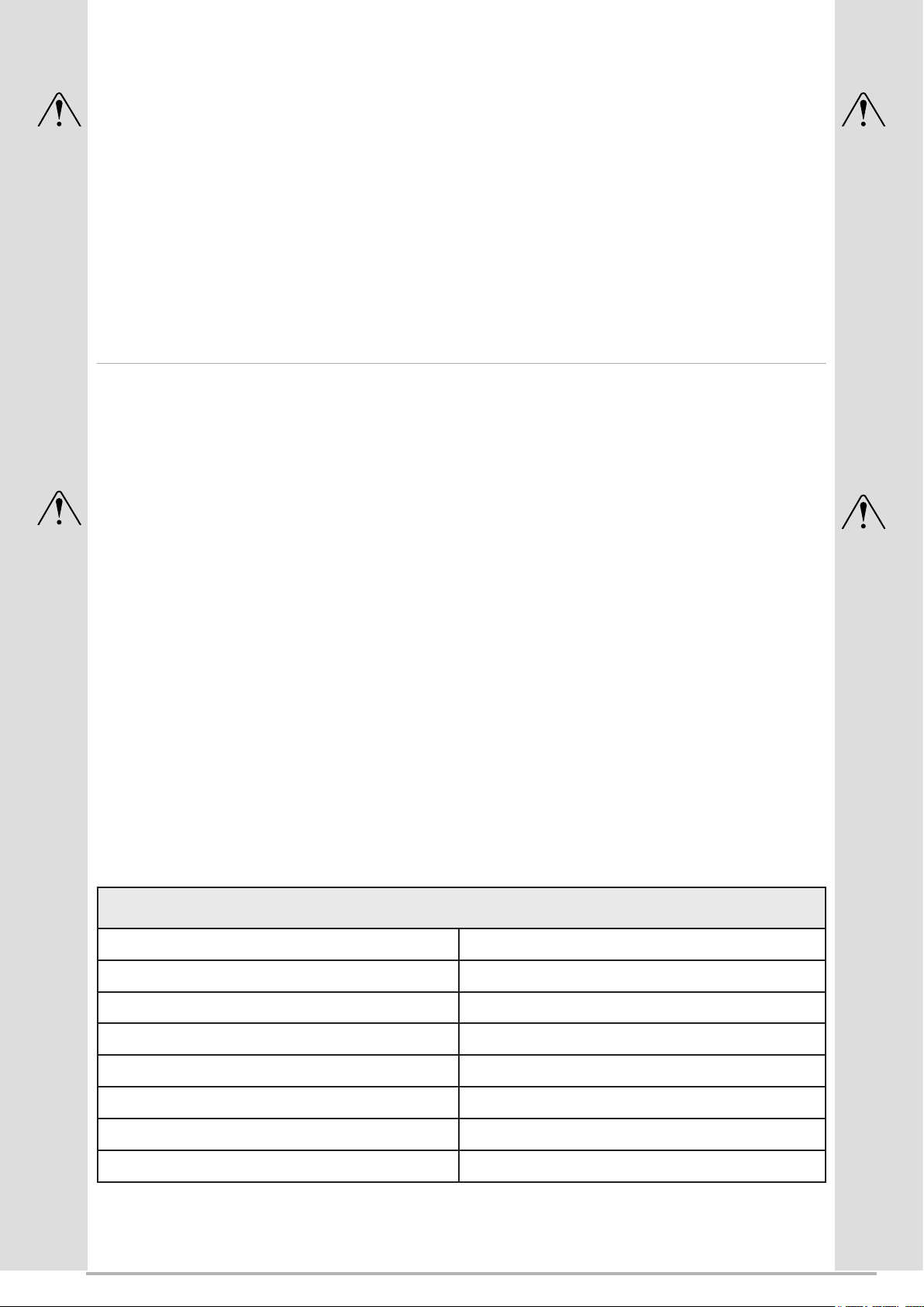
The maximum authorised values are as follows:
Use glycol water if the room where the primary/secondary storage tank(s) is/are installed
is not frost-free; we recommend that this situation be temporary so as not to alter the
system’s
MAXIMUM AUTHORISED PHYSICAL-CHEMICAL CHARACTERISTICS AUTHORISED FOR THE INSTALLATION
WATER
PH 7.5 - 9
Electrical conductivity 100 - 500 μS/cm
Total hardness 8.0 - 15.1 °f
Temperature ˂ 65°C
Oxygen content ˂ 0.1 ppm
Max. quantity of glycol 40%
Iron (Fe) < 0.3 ppm
Chlorine ions (Cl-) < 50 ppm
10 / 78 00U07362410-A_EN 01.07.2022 11 / 78
Percentage of
glycol Freezing point [°C] Eciency cor-
recon factor
Absorbed power
correcon factor
Water ow rate
correcon factor
Loss of head cor-
recon factor
10% -3.2 0.985 1 1.02 1.08
20% -7.8 0.98 0.99 1.05 1.12
30% -14.1 0.97 0.98 1.10 1.22
40% -22.3 0.965 0.97 1.14 1.25
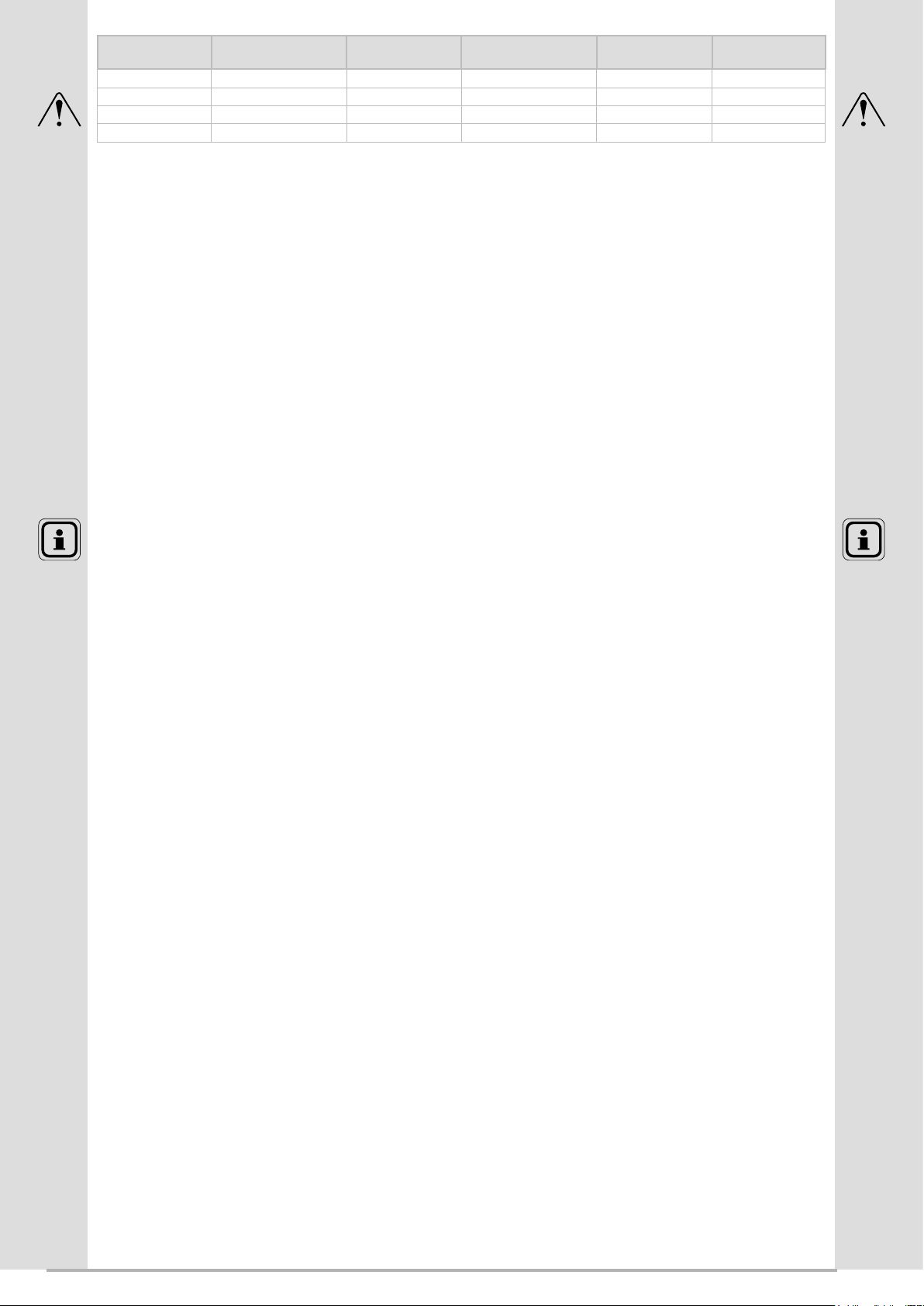
performance permanently. Do not forget to ush the system once the room is frost-free.
If glycol water is used, plan an annual control of the glycol quality. Use monopropylene
type glycol only. The recommended concentration should not exceed 40%.
If glycol is not used, trace the pipes electrically outside.
• In certain installations, the presence of dierent metals can cause corrosion
problems; in this case, the formation of metal particles and sludge in the
hydraulic circuit is seen.
-Please refer to the chapter “Treatment of domestic and heating water” in our price
catalogue
• It is also necessary to ensure that the treated water does not become aggressive
for the circuit.
■Electrical connections
Ensure that the general electrical power supply has been cut o before starting any
repair work.
Characteristics of the electrical power supply
The electrical installation must be conducted in accordance with the regulations in eect
and in particular to current I.E.E. (BS7671) Wiring Regulations
The electrical installation must be equipped with a dierential protection.
This appliance is designed to operate under a nominal voltage of 400 V +/- 10%, 50 Hz.
For installations without neutral, a galvanic isolating transformer must be used that is
earthed on the secondary side.
The electrical connections will only be made when all of the other assembly operations
(attachment, assembly,...) have been carried out.
Never use a socket for the power supply.
CAUTION:
The contract with the energy supplier must cover the maximum electrical requirement of
the installation.
The outdoor unit must be supplied directly (without external switch) by a dedicated line
protected at the start by a dedicated isolator switch. (Seer “Current source” paragraph).
Andere Handbücher für TYNEHAM AHP60
1
Inhaltsverzeichnis
Andere Hamworthy Wärmepumpe Handbücher

Beliebte Wärmepumpe Handbücher anderer Marken


Mitsubishi Electric
Mitsubishi Electric PUZ-SWM60VAA Bedienungsanleitung

Dimplex
Dimplex LI 16I-TUR Benutzerhandbuch

Carrier
Carrier WSHP Open v3 Kurzanleitung zur Einrichtung

TGM
TGM CTV14CN018A Bedienungsanleitung

Carrier
Carrier 38MGQ Series Bedienungsanleitung

Kokido
Kokido K2O K880BX/EU Fehlerbehebungshandbuch


