Vacuum valve (weight loaded)
12503
BA_012503.03_EN
3 / 10 Albert Handtmann Armaturenfabrik GmbH & Co. KG 2017-03-23
Pos: 10 .1 /Tec hnisc he Doku menta tion/Ü bers chrif ten/ 1./Lie ferung und L eist ung, Lag erung ( 3) @ 0\mod_1215179940062_20.docx@ 440@ 1 @ 1
3Delivery, Completeness, Storage
Pos: 10 .2 /Tec hnisc he Doku menta tion/ Betr iebsa nleitu ngen/ Liefer ung un d Leist ung, L ager ung/Lie ferung un d Leist ung, Lag erung @ 0\mod_1215178430359_20.docx@ 316@ @1
•Check the data of the delivery note for factual correctness and the material for
completeness. We regret that money cannot be refunded after purchase.
•Always check the material for transport damages. Possible damages have
to be informed immediately.
•Store the material in a dry place and if possible in its original packaging.
Pos: 11 /T echnis che Do kumen tation/ Übers chrift en/1. /Mont age, B etrieb, W artung ( 4) @ 0\mod_1215179594328_20.docx@ 364 @ 1 @ 1
4Installation, Operation, Maintenance
Pos: 12 /T ech nisc he D ok umen ta tion/ Be trie bsa nl eitung en/ Mon tag e, Betri eb, Wart ung /M ontag e/1 250 3/al lg emei ne H in weis e @ 0\mod_1221477562521_20.docx@1206 @ @ 1
Important notice !
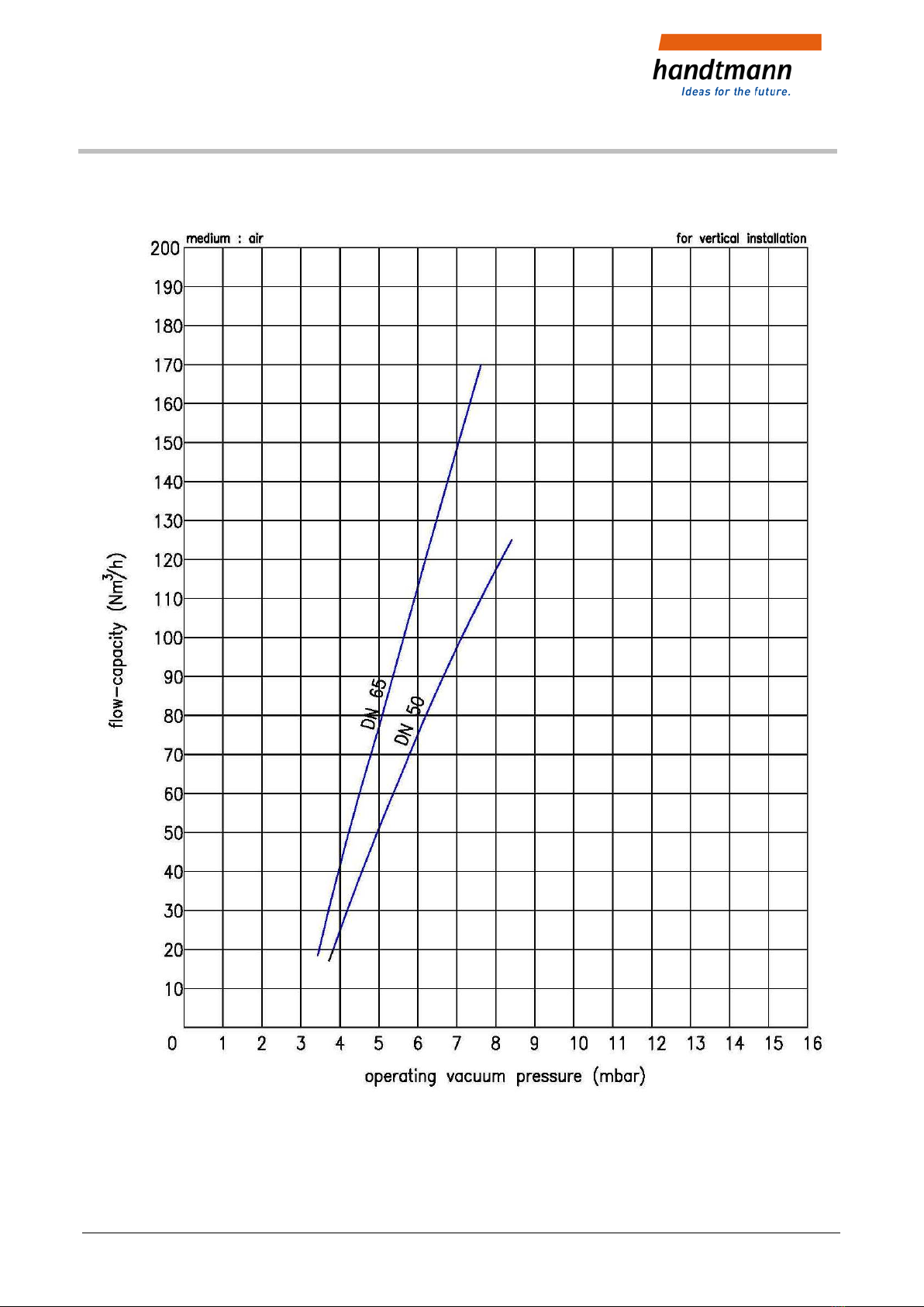
•Valve/component suitable for vertical installation.
•Valve opens at a negative pressure of 3-5 mbar (30-50 mm WC).
Pressure compensation to ambient pressure by draw in air.
The valve will be closed by counter pressure of the weight.
•For higher temperatures (>40°C) use stainless steel (3) valve cone
(for DN 65).
•To avoid mistakes during assembly/disassembly, pay attention to the operating
instructions respectively the type plate
Pos:13.1/TechnischeDokumentation/Übers chr ift en/ 1. 1/M ont age hin weis e @ 0\mod_1215178399000_20.docx@ 395 @ 2 @ 1
4.1 Assembly instructions
Pos:13.2/TechnischeDokumentation/Betriebsanleitungen/Montage,Betrieb,Wartung/Montage/Montage Heizeinrichtung@ 0\mod_1215764074241_20.docx@ 623 @ @ 1
Execution with heating device:
•The heating insets may only be connected according to attached scheme. Pay
attention to the connecting voltage!
•Do not remove the heating inset from the flange during function test
(heating capacity). It may get damaged by overheating.
Pos: 14 /T ech nisc he D ok umen ta tion/ Be trie bsa nl eitung en/ Mon tag e, Betri eb, Wart ung /M ontag e/M ont age Anlü ft ung @ 0\mod_1221051012496_20.docx@ 1105@ @ 1
Execution with lifting device:
•Pneumatic lifting cylinder for function test and for lifting the valve cone
during CIP. The stroke of the lifting cylinder is factory preset.
So the stroke of the valve cone is limited to about 3 mm.
With too large stroke, the emerging splash amount increases.
•Suitable for treated compressed air, max. 6 bar
•Throttle of air inlet has to be adjusted upon setting into operation.
•Compressed air supply: air hose Ø 6/4.