ULTRA RELIABLE SINCE 1956 P. 3
MODEL L-21 HARWIL CORPORATION
541 KINETIC DRIVE, OXNARD, CA 93030
TEL: (805) 988-6800 FAX: (805) 988-6804
EMAIL: HARWIL@HARWIL.COM
LOW LIQUID LEVEL ALARM
Fig 1: Wiring schematic for power applied to load when
liquid level is less than set point (power to load interrupted
when level increases to above set point).
Decreasing liquid level moves actuator in direction shown.
HIGH LIQUID LEVEL ALARM
Fig 2: Wiring schematic for power applied to load when
liquid level is greater than set point (power to load inter-
rupted when level decreases to below set point).
Increasing liquid level moves actuator in direction shown.
MICROSWITCH
NC
NO
(HOT)
LOAD
LINE
COM
MICROSWITCH
NC
NO
(HOT)
LOAD
LINE
COM
Microswitch actuation point may be monitored by an audible click or with an ohmmeter before connecting line power to the
switch terminals or by monitoring the voltage supplied to the load through the microswitch.
* Pump Up wiring diagram same as low level alarm shown in Fig. 1
* Pump Down wiring diagram same as high level alarm shown in Fig. 2
* Electrical Wiring (Strain Relief Grommet):
Step 1) Remove the gland nut, grommet, and switch cover.
Step 2) Strip the outer jacket of the electrical cord back
approximately 1¼” (inches). Strip insulation from
individual conductors back approximately ¼”
(inch).
Step 3) Slip-on terminals are supplied with each switch.
Remove from switch terminals and crimp on or solder to electrical leads.
Step 4) Feed the electrical cable through the strain relief nut, grommet, and switch cover.
Step 5) Apply slip-on terminals to appropriate contacts of microswitch. Slide cover down the cable and fasten it to the body
of the switch with four (4) screws provided. Slide grommet down the cable and push the grommet into the tapered
end of the cover. Hold the cable jacket to prevent rotation and thread gland nut firmly onto cover.
¼”
1¼”
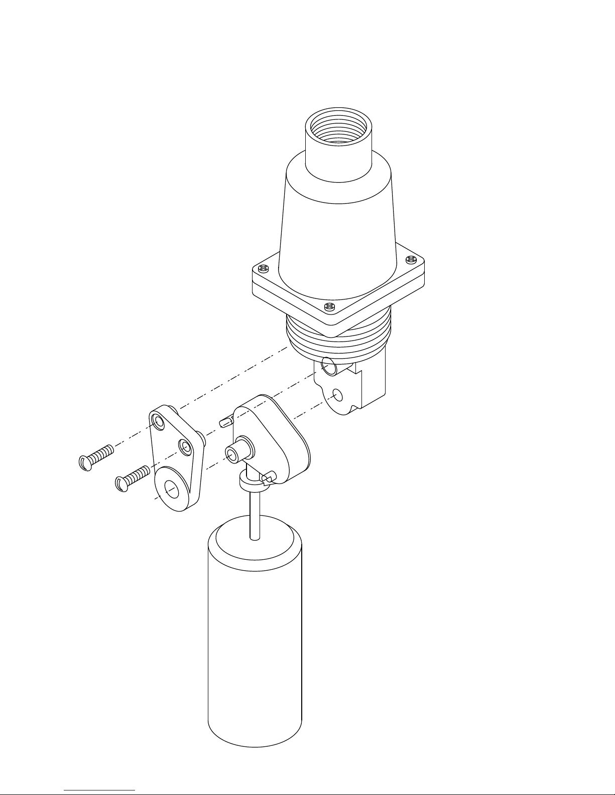
* Electrical Wiring (‘F’ Cover):
Step 1) Remove switch cover.
Step 2) Strip the outer jacket of the electrical cord back
approximately 1¼” (inches). Strip insulation from in-
dividual conductors back approximately ¼” (inch).
Step 3) Slip-on terminals are supplied with each switch. Re-
move from switch terminals and crimp on or solder
to electrical leads.
Step 4) Thread user supplied ½” flexible conduit fitting into
½” female thread on end of cover. Feed electrical
cable through conduit fitting.
Step 5) Apply slip-on terminals to appropriate male spade
contacts on microswitch. Slide cover down cable
and fasten to body of switch with four (4) screws
provided. Be sure to install the “O” ring between
the body and cover. Connect flexible ½” metal or
plastic conduit-to-conduit fitting on end of cover per
standard procedure.