HAUL MASTER 62645 Montageanleitung

Visit our website at: http://www.harborfreight.com
WARNING!
IMPORTANT INFORMATION
This trailer’s Hitch Coupler MUST be
properly secured to the hitch ball of the towing
vehicle. After assembly and attachment, pull
up and down on the Hitch Coupler to make
sure the hitch ball is fitting snugly in the Hitch
Coupler. There must be no play between the
hitch ball and the Hitch Coupler. If there is
play, tighten the Adjustment Nut until no play
is present. If the Adjustment Nut is too tight,
the Handle will not lock. Carefully read and
follow the complete instructions in this
manual BEFORE setup or use.
If the coupler is not secured
properly, the ball could come loose
while the trailer is in motion, possibly
causing property damage, SERIOUS
PERSONAL INJURY, or DEATH.
ITEM 62645
Owner’s Manual & Safety Instructions
Save This Manual Keep this manual for the safety warnings and precautions, assembly,
operating, inspection, maintenance and cleaning procedures. Write the product’s serial number in the
back of the manual near the assembly diagram (or month and year of purchase if product has no number).
Keep this manual and the receipt in a safe and dry place for future reference.
When unpacking, make sure that the product is intact
and undamaged. If any parts are missing or broken,
please call 1-888-866-5797 as soon as possible.
Copyright©2015 by Harbor Freight Tools®. All rights reserved.
No portion of this manual or any artwork contained herein may be reproduced in
any shape or form without the express written consent of Harbor Freight Tools.
Diagrams within this manual may not be drawn proportionally. Due to continuing
improvements, actual product may differ slightly from the product described herein.
Tools required for assembly and service may not be included.
Read this material before using this product.
Failure to do so can result in serious injury.
SAVE THIS MANUAL.
REV 15f

Item 62645 For technical questions, please call 1-888-866-5797. PAGE 2
CONTENTS
SPECIFICATIONS.................................................................................... 3
GENERAL SAFETY WARNINGS AND PRECAUTIONS ........................ 3
SPECIFIC PRODUCT WARNINGS AND PRECAUTIONS ..................... 4
ASSEMBLY INSTRUCTIONS.................................................................. 6
OPERATING INSTRUCTIONS ............................................................... 15
TIRE INFORMATION .............................................................................. 16
Tire Terminology Glossary..................................................................................16
Tire Markings........................................................................................................17
Tire Inflation and Load Limit...............................................................................18
TIRE CARE ............................................................................................. 19
Checking Tire Pressure.......................................................................................19
Steps for Maintaining Proper Tire Pressure......................................................19
Tire Size ................................................................................................................20
Tire Tread ..............................................................................................................20
Tire Rotation .........................................................................................................20
Tire Balance and Alignment................................................................................20
Tire Repair ............................................................................................................20
VEHICLE LOAD LIMIT ........................................................................... 21
Steps for Determining Correct Load Limit.........................................................21
INSPECTION, MAINTENANCE, AND CLEANING ................................ 21
PARTS LIST AND DIAGRAMS............................................................... 22
Parts List...............................................................................................................22
Assembly Diagram...............................................................................................23
Wiring Diagram.....................................................................................................24

Item 62645 For technical questions, please call 1-888-866-5797. PAGE 3
SPECIFICATIONS
Maximum Payload Capacity 1,090 lb.
GVWR 1,250 lb.
Net Weight 151 lb.
Rim Size 4.80/4.00 - 12″ w/4 Lug Nut Pattern
Tire Size 4.80 x 12, 4PR
Tire Pressure 60 PSI, cold
Hitch Ball 1-7/8″, Class I
Bed Frame 40-1/2″ x 48″
Axle Clearance 7″
Tongue Height 12-1/2″
Safety Chain 1″ Link (Welded)
7/32″ Diameter x 42″ L w/S Hooks
Lights & Wiring 12 VDC / DOT Approved
GENERAL SAFETY WARNINGS AND PRECAUTIONS
1. KEEP WORK AREA CLEAN AND DRY. Cluttered, damp, or wet work areas invite injuries.
2. KEEP CHILDREN AWAY FROM WORK AREA. Do
not allow children to handle this product.
3. STORE IDLE EQUIPMENT. When not in use, tools and equipment
should be stored in a dry location to inhibit rust. Always lock up
tools and equipment, and keep out of reach of children.
4. DO NOT USE THIS PRODUCT IF UNDER THE INFLUENCE OF ALCOHOL OR DRUGS.
Read warning labels on prescriptions to determine if your judgement or
reflexes are impaired while taking drugs. If there is any
doubt, do not attempt to use this product.
5. USE EYE PROTECTION. Wear ANSI approved safety impact eye goggles when
assembling this product. ANSI approved safety impact eye
goggles are available from Harbor Freight Tools.
6. DRESS SAFELY. Do not wear loose clothing or jewelry, as they can become caught
in moving parts. Wear a protective hair covering to prevent long hair from becoming
caught in moving parts. If wearing a long-sleeve shirt, roll sleeves up above elbows.
7. DO NOT OVERREACH. Keep proper footing and balance at
all times to prevent tripping, falling, back injury, etc.
8. INDUSTRIAL APPLICATIONS MUST FOLLOW OSHA REQUIREMENTS.
9. STAY ALERT. Watch what you are doing at all times. Use common sense. Do
not use this product when you are tired or distracted from the job at hand.
10. CHECK FOR DAMAGED PARTS. Before using this product, carefully
check that it will operate properly and perform its intended function. Check
for damaged parts and any other conditions that may affect the operation of
this product. Replace or repair damaged or worn parts immediately.
11. REPLACEMENT PARTS AND ACCESSORIES: When servicing, use only
identical replacement parts. Only use accessories intended for use with this
product. Approved accessories are available from Harbor Freight Tools.

Item 62645 For technical questions, please call 1-888-866-5797. PAGE 4
12. MAINTAIN THIS PRODUCT WITH CARE. Keep this product
clean and dry for better and safer performance.
13. MAINTENANCE: For your safety, service and maintenance
should be performed regularly by a qualified technician.
14. USE THE RIGHT TOOL FOR THE JOB. Do not attempt to force small equipment
to do the work of larger industrial equipment. There are certain applications for
which this equipment was designed. It will do the job better and more safely
at the capacity for which it was intended. Do not modify this equipment, and
do not use this equipment for a purpose for which it was not intended.
15. WARNING: The warnings, precautions, and instructions discussed in this
manual cannot cover all possible conditions and situations that may occur. The
operator must understand that common sense and caution are factors, which
cannot be built into this product, but must be supplied by the operator.
SPECIFIC PRODUCT WARNINGS AND PRECAUTIONS
1. TO AVOID PERSONAL INJURY AND/OR PROPERTY DAMAGE, DO NOT
EXCEED THE TRAILER’S MAXIMUM CAPACITY PAYLOAD OF 1,090 LBS.
2. BEFORE EACH USE, ALWAYS EXAMINE THE TRAILER FOR PROPER
TIRE (16) AIR PRESSURE, DAMAGED TAILLIGHTS (29, 29A), DAMAGED
SIDE RUNNING LIGHTS (30), LOOSE BOLTS AND NUTS, STRUCTURAL
CRACKS, BENDS, AND ANY OTHER CONDITION THAT MAY AFFECT ITS
SAFE OPERATION. Do not use the Trailer even if minor damage appears.
3. NEVER ALLOW ADULTS, CHILDREN, OR PETS TO RIDE IN THE TRAILER.
4. BEFORE EACH USE, ALWAYS ATTACH THE SAFETY CHAIN (25) OF THE TRAILER
TO THE TOWING VEHICLE. Make sure the Safety Chain is attached to the towing vehicle
with the same length for each side. Do not allow the Safety Chain to drag on the ground.
5. ALWAYS CHECK TO MAKE SURE THE PAYLOAD BEING TRANSPORTED
IS PROPERLY AND SAFELY SECURED IN THE TRAILER. Load the Trailer
evenly from side to side with 60% of the load forward of the Axle (12).
6. MAKE SURE THE TOWING VEHICLE IS CAPABLE OF TOWING THE TRAILER AND
ITS PAYLOAD. Make sure the hitch on the towing vehicle is capable of towing the Trailer
and its payload. The towing capacity of the hitch is typically stamped on the hitch drawbar.
7. MAKE SURE THE COUPLER (23) AND THE VEHICLE’S BALL HITCH (not
included) ARE OF EQUAL MATING SIZE (1-7/8″) AND ARE RATED EQUAL TO
OR GREATER THAN THE WEIGHT OF THE TRAILER AND ITS PAYLOAD.
8. DO NOT EXCEED 45 MILES PER HOUR WHEN TOWING THE TRAILER.
Excess speed is a major cause of vehicle-trailer accidents.
9. THE TAILLIGHT BULBS SUPPLIED WITH THIS TRAILER ARE FOR
A 12 VOLT DC ELECTRICAL SYSTEM ONLY. Do not attempt to power
the Light Bulbs with any other type or voltage electrical current.
10. WHENEVER POSSIBLE, PARK THE TRAILER ON A FLAT, LEVEL, PAVED, SURFACE
AND CHOCK BOTH TIRES TO KEEP THE TRAILER FROM ACCIDENTLY MOVING.
11. TRAILER LICENSING NOTICE: Some states may consider this Trailer a vehicle
requiring registration, licensing, and titling. Check with your State Department of Motor
Vehicles for information and guidance on registering, licensing, and titling the Trailer.

Item 62645 For technical questions, please call 1-888-866-5797. PAGE 5
12. MAINTAIN LABELS AND NAMEPLATES ON THE TRAILER. These carry important
information. If unreadable or missing, contact Harbor Freight Tools for a replacement.
13. REPORTING SAFETY DEFECTS: If you believe your vehicle has a defect which could
cause a crash or could cause injury or death, you should immediately inform the National
Highway Traffic Safety Administration (NHTSA) in addition to notifying the manufacturer,
Changzhou Nanxiashu Tool Company. If NHTSA receives similar complaints, it may
open an investigation, and if it finds that a safety defect exists in a group of vehicles, it
may order a recall and remedy campaign. However, NHTSA cannot become involved in
individual problems between you, Harbor Freight Tools, or the manufacturer. To contact

NHTSA, you may either call the Auto Safety Hotline toll-free at 424-9393 or 202-366-0123
or write NHTSA, U.S. Department, 400 7th Street SW NSA-11, Washington, D.C. 20590.

You may also obtain other information about motor vehicle safety from the Hotline.

Item 62645 For technical questions, please call 1-888-866-5797. PAGE 6
ASSEMBLY INSTRUCTIONS
Note: For additional references to the parts listed on the following pages, refer to
the Assembly Diagram near the end of this manual. Be sure to read
the Bearing Packing instructions on the last page of this manual.
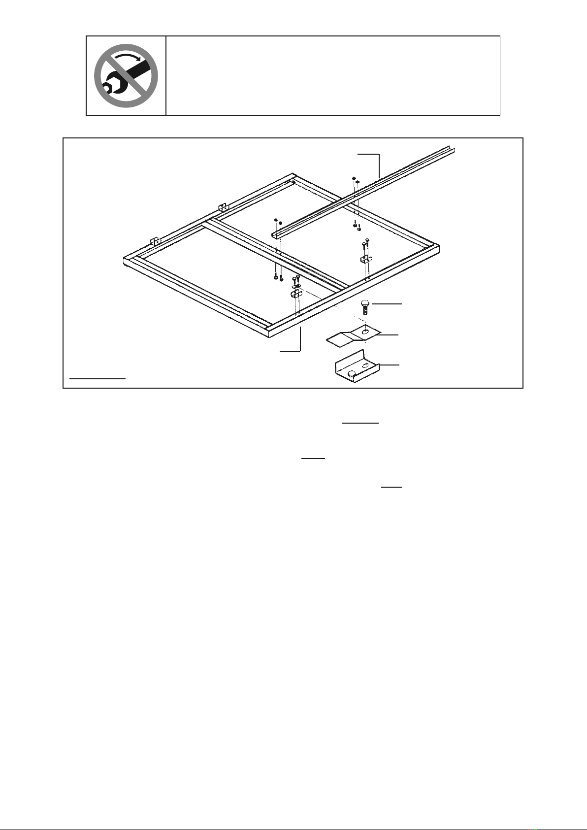
1.
LEFT
SIDE RAIL
(5)
RIGHT
SIDE RAIL
(5A)
BOLT
(1)
LOCK NUT (3)
(NOT SHOWN)
FRONT
REAR
FIGURE A
CROSS
MEMBER
(4)
CROSS
MEMBER
(4)
CROSS
MEMBER
(4)
Lay out three Cross Members (4), the Right Side Rail (5A), and the Left Side Rail (5). Then
assemble the parts, using Bolts (1) and Lock Nuts (3).
(See Figure A.)
DON’T TIGHTEN YET!
TO MAKE ASSEMBLY EASIER, wait until assembly is
complete and all hardware is in place before tightening
any nut or bolt. Leave hardware snug until then.

Item 62645 For technical questions, please call 1-888-866-5797. PAGE 7
2.
BOLT
(1)
LOCK NUT (3)
(NOT SHOWN)
SPRING
HANGER
(7)
SPRING SIDE PLATE (8)
REAR
FRONT
TOW BAR
(6)
FIGURE B
Turn the frame assembly upside down. Attach the Tow Bar (6) to the
frame assembly, using Bolts (1) and Lock Nuts (3). NOTE: Observe
the direction in which the Bolts are inserted. (See Figure B.)
3. Attach two of the Spring Hangers (7) to the front portions of the Right Side Rail (5A) and
the Left Side Rail (5), using Bolts (1) and Lock Nuts (3). Then attach the remaining two
Spring Hangers, each with a Spring Side Plate (8), to the rear portions of the Right Side
Rail (5A) and the Left Side Rail (5), using Bolts (1) and Lock Nuts (3). (See Figure B.)
DON’T TIGHTEN YET!
TO MAKE ASSEMBLY EASIER, wait until assembly is
complete and all hardware is in place before tightening
any nut or bolt. Leave hardware snug until then.

Item 62645 For technical questions, please call 1-888-866-5797. PAGE 8
4.
FIGURE C
U-BOLT (13)
AXLE (12)
SLIPPER SPRING (9)
SPRING HANGER (7)
NUT (11)
LEFT SIDE RAIL (5)
FRONT
REAR
LOCK NUT (3)
SPRING
PLATE
(14)
COTTER PIN (33)
COTTER PIN (33)
BOLT (10)
BOLT (10)
NUT
(11)
Place the Slipper Springs (9) in the Spring Hangers (7).
Secure the Slipper Springs to the Spring Hangers, using Bolts (10)
and Nuts (11). Then, insert a Cotter Pin (33) through the hole in
the end of the Bolts and spread it. (See Figure C.)
5. Place the Axle (12) on top of the Slipper Springs (9). Position a Spring Plate
(14) under the Slipper Springs. Place two U-Bolts (13) over each end of the Axle
and each Slipper Spring. Then insert the U-Bolts through the holes in the Spring
Plates and secure the Spring assembly, using Lock Nuts (3). (See Figure C.)
DON’T TIGHTEN YET!
TO MAKE ASSEMBLY EASIER, wait until assembly is
complete and all hardware is in place before tightening
any nut or bolt. Leave hardware snug until then.

Item 62645 For technical questions, please call 1-888-866-5797. PAGE 9
COTTER PIN (21)
LUG NUT (17)
LUG NUT
(17)
BEARING (18)
3/4″ WASHER
(19)
CASTLE NUT
(20)
DUST CAP
(22)
TIRE (16)
HUB
(15)
GREASE
FITTING
(35)
AXLE
(12) SPINDLE
FIGURE D
6. Attach the Grease Fitting (35) to the Hub (15). (See Figure D.)
NOTE: Every 2,000 to 3,000 miles of use, lubricate the Hub
assembly with a heavy duty bearing grease.
7. Carefully slide the Hubs (15) over the Spindles at each end of the Axle
(12). Follow the Bearing Packing Instructions as explained on the last
page of this manual. Insert the Bearing (18) and a 3/4″ Flat Washer (19) on
the Spindles. Screw a Castle Nut (20) tightly onto each Spindle. Then back
the Castle Nuts off slightly so that the Hubs (15) can just move freely.
8. Place a Tire (16) on each Hub (15). Secure the Tires to the Hubs, using four
Lug Nuts (17) per Tire. NOTE: Tighten (torque) the Lug Nuts to at least 90 ft-lb.
9. Insert a Cotter Pin (21) through the hole at the end of each
Spindle of the Axle (12) and spread the Cotter Pin.
10. Press each Dust Cap (22) onto each Hub (15).
11. With assistance, turn the Trailer over so that its Tires (16) are on the floor/ground surface.
DON’T TIGHTEN YET!
TO MAKE ASSEMBLY EASIER, wait until assembly is complete
and all hardware is in place before tightening any nut or bolt,
except wheel lugs. Leave hardware snug until then.

Item 62645 For technical questions, please call 1-888-866-5797. PAGE 10
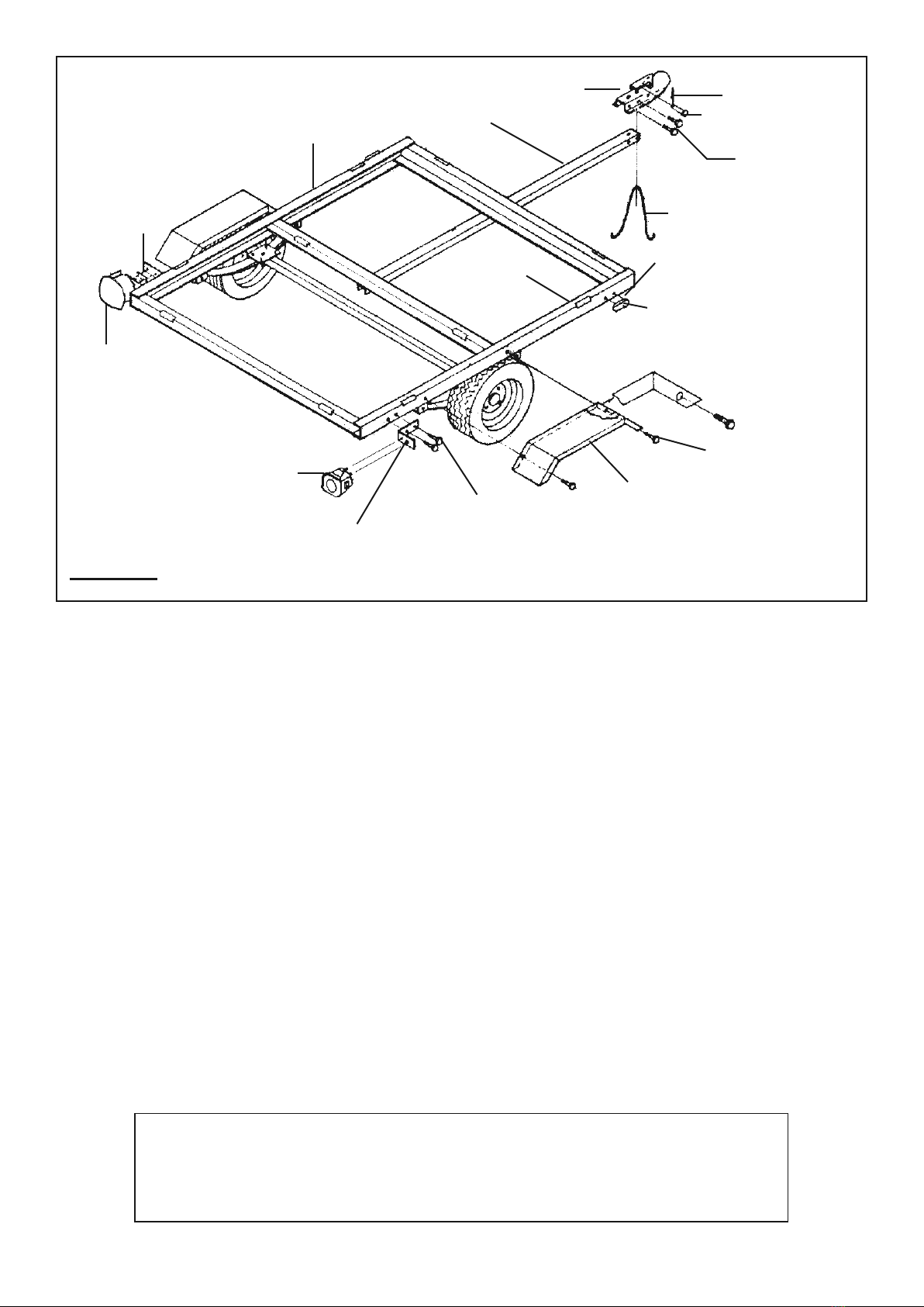
RIGHT
SIDE RAIL
(5A)
FENDER (34)
BOLT (1)
LOCK NUT (3)
RIGHT
TAILLIGHT
(29A)
TAILLIGHT
BRACKET
(27)
BOLT (1)
LOCK NUT (3)
LEFT
SIDE RAIL
(5)
LEFT
TAILLIGHT
(29)
LICENSE PLATE
BRACKET
(28)
COUPLER
(23) R-PIN (36)
SAFETY PIN (37)
BOLT (24)
NUT (3)
SAFETY CHAIN (25)
TOW BAR
(6)
SIDE RUNNING LIGHT
(30)
SELF TAPPING SCREW
(31)
FIGURE E
12. Disassemble two Bolts (24) and Chain (25) from the
Coupler if they are installed. (See Figure E.)
13. Place the Coupler on the Tow Bar (6), and attach it using a Bolt (24) through
the rear holes on the side of the coupler, secured by a Lock Nut (3).
14. Locate Chain’s (25) center link and insert a Bolt (24) through it. Install that Bolt
through the front holes on the side of the Coupler, and secure it with a Lock Nut (3).
15. Attach the Taillight Brackets (27) to the Right Side Rail (5A) and
Left Side Rail (5), using Bolts (1) and Lock Nuts (3).
16. Attach the License Plate Bracket (28) and Left Taillight (29) to the
Left Side Rail (5), using Bolts (1) and Lock Nuts (3).
17. Attach the Right Taillight (29A) to the Right Side Rail (5A), using Bolts (1) and Lock Nuts (3).
18. Remove the Lens from a Side Running Light (30). Insert the Wire Lead of
the Side Running Light through the center hole of the Right Side Rail (5A).
Attach the Side Running Light to the Right Side Rail, using the Self Tapping
Screws (31). Then, reattach the Lens to the Side Running Light. Repeat this
step for the remaining Side Running Light and the Left Side Rail (5).
19. Attach a Fender (34) to the Right Side Rail (5A) and Left
Side Rail (5), using Bolts (1) and Lock Nuts (3).
TIGHTEN ALL HARDWARE!
Now that frame is completely assembled, retrace all assembly steps
and make sure that all hardware is properly wrench-tightened.
Also, tighten lug nuts/lug bolts to 90 ft-lb.
Inhaltsverzeichnis
Andere HAUL MASTER Nutzfahrzeug Handbücher

HAUL MASTER
HAUL MASTER 58702 Bedienungsanleitung

HAUL MASTER
HAUL MASTER 94564 Bedienungsanleitung

HAUL MASTER
HAUL MASTER 90154 Montageanleitung

HAUL MASTER
HAUL MASTER 62665 Montageanleitung

HAUL MASTER
HAUL MASTER 95419 Bedienungsanleitung

HAUL MASTER
HAUL MASTER 2948 Stücklistenhandbuch

HAUL MASTER
HAUL MASTER 92174 Stücklistenhandbuch

HAUL MASTER
HAUL MASTER 42708 Bedienungsanleitung

HAUL MASTER
HAUL MASTER 90154 Bedienungsanleitung

HAUL MASTER
HAUL MASTER 66771 Benutzerhandbuch