HEX8-150 ESC USER MANUAL
2. Programming the ESC with the LED program box:
08 Factory Reset
09 Trouble Shooting
2.
3.
4.
5.
6.
7.
8.
9.
10.
11.
The portable program card is an optional accessory applicable for field use. It’s friendly interface makes the
ESC programming quick and easy. Before programming, connect the ESC to the program card with a cable that
uses a JR male connector on each end, and then turn on the ESC; all programmable items will show up a few
seconds later. You can select the item you want to program and the setting you want to choose via “ITEM” and
“VALUE” buttons on the program card. Then press the “OK” button to save all new settings to your ESC.
The programming port of this ESC is also the fan port, so you need to unplug the fan first and then plug one end of the
programming cable into the PRG/FAN port. The other end of the programming cable plugs into the ESC port on the LED
program box. Do NOT use the throttle control cable (also called Rx cable) on the ESC to connect to
the program card/box. This may cause damage and the program card/box won’t function.
1. Restore the default values with the SET button:
Press and hold the SET button for over 3 seconds anytime when the throttle trigger is at the neutral position (except during the ESC
calibration and programming). This will factory reset your ESC. Red & Green LEDs will flash simultaneously, indicating you have successfully restored all
default values within your ESC. Once you power the ESC off, and then back on, your settings will be back in the default mode.
2) Restore the default values with the LED program card:
After connecting the program card to the ESC, press the “RESET” button and the “OK” button on the program card to factory reset your ESC
2017.08.08Page 2 of 2
LiPo Cells:
We strongly recommend setting this parameter manually instead of using the default parameter “Auto Calc.” (which means calculating the LiPo cells
automatically). The ESC can only identify 3S, 4S, 6S LiPo packs when setting this parameter to “Auto Calc.”. After the ESC is powered on, if the battery
voltage is below 13.6V, it will be identified as a 3S. If the voltage is from 13.6V to 17.6V, it will be identified as a 4S. If the voltage is from 17.6V to 26.5V, it
will be identified as a 6S.
Note 2: This ESC is not intended for 2S operation. Even if you can set the “LiPo Cells” to 2S, it still does not work. When using a NiMH pack, you need to
set “LiPo Cells” to “Auto Calc.” and “Cutoff Voltage” to “Disabled”.
Low Voltage Cut-Off:
This sets the voltage at which the ESC lowers or removes power to the motor in order to keep the LiPo battery at a safe minimum voltage. The ESC will
constantly monitor the battery voltage and when the voltage drops below the cutoff threshold per cell, the ESC will immediately reduce the power to 50%
and then to 0% ten seconds later. The red LED will flash a short, single flash that repeats to indicate the low-voltage cutoff protection is activated. If using a
NiMH pack, set the “Cutoff Voltage” to “Disabled”.
ESC Thermal/Overheat Protection:
The ESC will automatically cut off power output and the green LED will flash a short, single flash that repeats (* * *) when the temperature exceeds the
preset ESC thermal protection value that was selected in the menu. The output won’t resume until the temperature drops to a safe level.
Motor Thermal/Overheat Protection:
This item has been permanently “Disabled”.
Motor Rotation:
Pull the throttle trigger with the motor shaft facing you. The motor spins counter clockwise if this item is set to CCW; the motor spins clockwise if set to CW.
The (A/B/C) wiring order of motors from different manufacturers may vary, so the direction of the motor rotation may be opposite to what you expect. You
can adjust the “Motor Rotation” or swap any two (ESC-to-motor) wires if the motor runs in reverse.
BEC Voltage:
Option 1: 6.0V: Best setting for standard servos. Do not use this option with high voltage servos; otherwise your servos may not function normally due to
insufficient voltage.
Option 2: 7.4V: Best setting for high voltage servos. Do not use this option with standard servos; otherwise your servos may burn out from high voltage.
Brake Amount/ Max. Brake Force:
This ESC uses proportional braking; the position of the throttle trigger effects the amount of braking applied. This function sets the percentage value of
available braking power that is applied with full brake. Large amounts will shorten the braking distance but may damage your pinion and spur gears. Set it
to the least amount of braking you can successfully and safely drive with. The looser the driving surface, the less brake force you should use.
Reverse Amount/ Max. Reverse Force:
This effects how fast the vehicle will drive in reverse. We recommend a lower value to protect the mechanical and electrical components of the vehicle.
Start Mode / Punch:
This effects the initial starting force. You can choose from punch level 1 (very soft) to level 5 (very aggressive). Track condition, grip level, tire choice, and
driving style may effect the amount of punch you choose. Soft punch is useful for preventing tires from slipping during initial acceleration. Aggressive (level
4 and level 5) punch has strict requirements on a battery’s discharge capability (C-rating). This may affect initial vehicle movement if the battery discharges
slowly and cannot quickly provide the required current. If the car stutters or suddenly loses power with acceleration, the battery’s discharge capability is too
low and you need to use a higher rated battery, or reduce the punch on the ESC. Using a smaller pinion gear on the motor may also help.
Drag Brake:
Drag brake is the slight braking power produced when releasing the throttle trigger to neutral zone. This gently slows the vehicle down when you let off the
trigger. Properly set drag brake makes the vehicle easier to corner during races. (Attention! Drag brake will consume lots of power, so use it cautiously.)
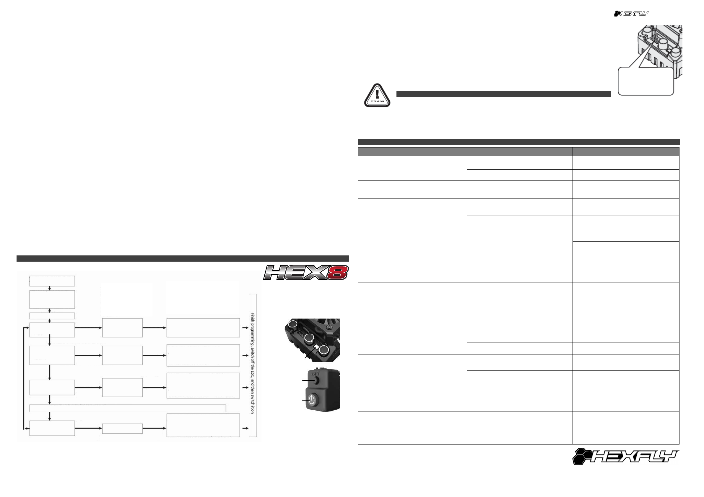
7 ESC Programming
1) Programming your ESC with the SET button
NOTE 2: In the program process, the motor will emit a “Beep” tone when the LED is flashing. The Hex8 uses a long flash and a long “Beep---” tone to
represent number “5”, to help identify the larger menu items. A long flash (Motor sounds “B---”) = the No.5 item. A long flash + a short flash (Motor
sounds “B--- B”) = the No.6 item. A long flash + 2 short flashes (Motor sounds “B--- B B”) = the No.7 item. A long flash + 3 short flashes (Motor sounds
“B--- B B B”) = the No.8 item. A long flash + 4 short flashes (Motor sounds “B--- B B B B”) = the No.9 item.
After releasing the
button to select the
desired adjustment, the
number of red LED
blinks, represents the
value within that
adjustment.
Click the SET button to choose the
value, the number of times the red
LED blinks indicates the option
number you are going to select.
7 ESC Programming
With the ESC switched o:
Turn on the transmitter
Press the ON/OFF
button while holding
the SET button to
Red LED ashes
Green LED ashes
once
Green LED ashes
twice
Green LED ashes
3 times
The following steps are just like the above steps…….
Green LED ashes
N times
“Running Mode”
“LiPo Cells”
“Low-Voltage
Cuto”
Enter the Nth item
Red LED ashes once =
"Forward with Brake”
Red LED ashes twice =
“Forward / Reverse with Brake”
Enter the Nth item
Red LED ashes once=“Auto Calculation”
Red LED ashes twice = “2S”
Red LED ashes 3 times = “3S”
Red LED ashes 4 times = “4S”
Red LED ashes 5 times = “6S”
Red LED ashes once =“Disabled”
Red LED ashes twice = “Auto (LOW)”
Red LED ashes 3 times = “Auto
(Intermediate)”
Red LED ashes 4 times = Auto (High)”
Press the SET button to choose the
value, the ash times of the Red LED
means the option number value.
(Once means the 1st option,
twice means the 2nd option, etc.)
Release the
SET Button
Release the
SET Button
Release the
SET Button
Release the
SET Button
Continue holding the SET button for 3 more seconds
Continue holding the SET button for 3 more seconds
Continue holding the SET button for 3 more seconds
Continue holding the SET button for 3 more seconds
Press the
SET Button
Press the
SET Button
Press the
SET Button
Press the
SET Button
Trouble Possible Reason Solution
After powering on the ESC, neither the motor
nor fan work.
No power is supplied to the ESC. Check if all ESC & battery connectors have been
well soldered and firmly connected.
The ESC switch is damaged Call customer service.
After the ESC is powered on, motor doesn’t work,
but emits “beep-beep-, beep-beep-” alert tone.
(Every “beep-beep-” hasa time interval of 1 second )
Input voltage is abnormal, too high or too low Check the voltage of the battery pack
After the ESC is powered on and finished LiPo
cell detection, the Geen LED flashed N times,
and the Red LED flashed rapidly.
The ESC didn't detect any throttle signal.
Check if the ESC throttle wire is correctly plugged
into receiver CH.2 and the transmitter is turned on
The neutral throttle value stored on your ESC is
different from the value stored on the transmitter
Re-calibrate the throttle range after you return
the throttle trigger to the neutral position.
The motor runs in the opposite direction when it is
accelerated.
The (ESC-to-motor) wiring order was incorrect. Swap any two wire connections between the ESC
and the motor.
Motor direction set wrong in the ESC (CW/CCW) Set the motor direction correctly (CW/CCW)
The motor suddenly stops running while in working
state.
The throttle signal is lost
Check the transmitter and the receiver
Check the signal wire from the throttle channel of
your receiver
The ESC has entered the Low Voltage Protection
Mode or Over-heat Protection Mode
Red LED flashing means Low Voltage. Green
LED flashing means Over-heat
The motor stuttered but couldn’t start.
Bad connection between the motor and the ESC.
Check all soldered connections, please
re-solder if necessary.
The ESC was damaged (some MOSFETs are
burnt).
Contact the distributor for repair or other customer
services.
The vehicle still has forward function, but no
reverse.
The throttle trim position on your transmitter
is not centered.
Re-calibrate the throttle neutral position. No LED
on the ESC will come on when the throttle trigger
is at the neutral position.
The “Running Mode” is set improperly. Set the “running mode” to “Forward/Reverse with
Brake”.
The ESC is damaged. Contact the distributor for repair or other
customer services.
The car ran forward / backward slowly when the
throttle trigger was at the neutral position.
The neutral position on the transmitter is not
stable, so signals are not stable either. Replace your transmitter
The ESC calibration is incorrect. Re-calibrate the throttle range or fine tune the
neutral position on the transmitter.
The LED program card keeps displaying 3 short
lines (- - -) after being connected to the ESC.
The programming card/box was connected to the
ESC via the throttle control cable (Rx cable).
It is wrong to use the Rx cable to connectthe
programming card/box. The programming port of
this ESC is also the fan port, so please connect
the ESC and programming card/box by plugging
the programming cable into the fan port.
When pressing the SET button to set the throttle
neutral position, the Green LED didn’t flash and
no beep was emitted, or you were unable to set
the full throttle endpoint or the full brake endpoint
after the neutral position was accepted.
The ESC throttle cable isn’t plugged into the
correct channel on the receiver.
Plug the throttle cable into the throttle (TH)
channel on your receiver (CH.2).
The ESC throttle cable is plugged in backwards. Plug in the throttle cable properly by referring to
relevant mark shown on your receiver.
9 Troubleshooting s
External Programming
port for connecting
program card
LED
SET Button
ON/OFF
Button


