Hypertherm powermax65 Referenzhandbuch

Powermax65®
Powermax85®
Power Switch Replacement
Remplacement de l’interrupteur
d’alimentation
Field Service Bulletin
Bulletin de service sur le terrain
806870 – Revision5 – November 2014
Révision5–Novembre2014

Powermax65/85 Power Switch rePlacement
Field Service Bulletin 1
Introduction
Purpose
This Field Service Bulletin describes the procedure for replacing the power switch on a Powermax65 or Powermax85.
Materials and tools
• Assorted Phillips®and TORX®screwdrivers
• Small knife or blade screwdriver
WARNING
ELECTRIC SHOCK CAN KILL
Disconnect electrical power before performing any maintenance. See the
Safety and Compliance Manual included with your system for more safety
precautions.
Caution: Static electricity can damage circuit boards.
• Use proper precautions when handling printed circuit boards.
– Store PC boards in anti-static containers.
– Wear a grounded wrist strap when handling PC boards.
Part number Description Quantity
005257 Power switch: 3-pole 600VAC 40A with auxiliary switch 1
075760 Plastite machine screw 4
108858 Handle: G4 CAM switch “I” type 1
110711 Label: Power switch 65A/85A 1
Kit 228644 contents (Powermax65 CSA)

Powermax65/85 Power Switch rePlacement
2Field Service Bulletin
Part number Description Quantity
003206 Power switch: 3-pole 600VAC 63A with auxiliary switch 1
075760 Plastite machine screw 4
108858 Handle: G4 CAM switch “I” type 1
110711 Label: Power switch 65A/85A 1
Part number Description Quantity
005650 Power switch: 3-pole 600VAC 25A 1
075760 Plastite machine screw 4
108858 Handle: G4 CAM switch “I” type 1
110711 Label: Power switch 65A/85A 1
Kit 228655 contents (Powermax85 CSA)
Kit 228671 contents (Powermax65/85 CE)

Powermax65/85 Power Switch rePlacement
Field Service Bulletin 3
Remove the power supply cover and Mylar®barrier
1. Turn OFF the power, disconnect the power cord, and disconnect the gas supply.
2. Remove the 8 small screws (2) from the power supply cover.
3. Remove the 8 large screws (1) from the power supply cover.
4. Lift the cover (3) off the power supply.
1
1 1
2
2
1
2
2
1
3
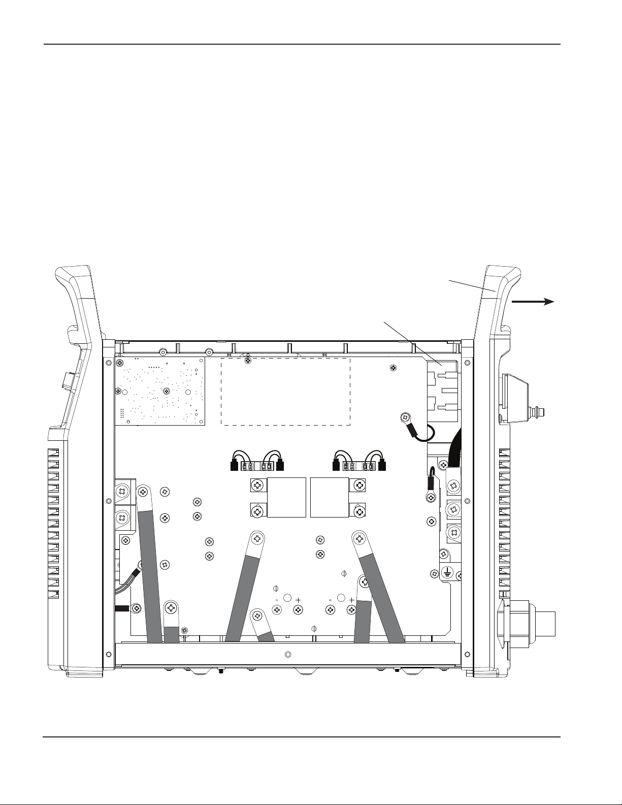
5. Remove the Mylar barrier from the power board side of the power supply. The Mylar barrier is flexible and can be
bent slightly for removal.
6. Remove the metal end panel bracket located on top of the center panel by pulling it straight up.
End panel bracket
Mylar barrier

Powermax65/85 Power Switch rePlacement
4Field Service Bulletin
Loosen the old power switch
1. Remove the handle screw that secures the power switch handle to the post.
2. Pull the power switch handle straight off the post and set aside.
3. If the optional RS485 connector is not installed, the label extends to the right side of the gas connector. (Refer to
the bottom figure below.) In this case, remove the top gas connector screw.
4. Use a knife or blade screwdriver to pry up the edge of the label.
5. Peel off the entire label to expose the four mounting screws that secure the power switch.
6. Remove the four power switch mounting screws.
The power switch is disengaged from the rear panel and may be removed from inside the power supply.
Handle screw
Power switch screws
(behind label)
Optional RS485
connector
Optional CNC
interface connector
Power switch screws
(behind label)
Left edge
of label
Left edge
of label
Top gas
connector
screw
Right edge of label
ends at perforation
Label
perforation
Right edge
of label
Top gas connector
screw through
hole on label
Power switch handle
Left half of label used when RS485 connector is installed
Full label used when RS485 connector is not installed

Powermax65/85 Power Switch rePlacement
Field Service Bulletin 5
WORK
LEAD
J13
J2
J1
J18J19
J27
J30
J23
J24
TP13
J29
TP11
TP12
Remove the old power switch (CE model)
1. On the fan side of the power supply, disconnect the gas supply tube from the air filter. Pull back the orange ring on
the push-to-connect tube connector and pull the tube out of the connector. Disconnecting the tube allows the rear
panel to move farther away from the power supply.
2. Carefully pull the top of the rear panel away from the power supply.
3. Slide the power switch out of the power supply. You will need to maneuver the power switch around the right edge
of the power board. Be sure not to damage any components.
4. Remove the power wires from the top and bottom of the old power switch.
5. Discard the old power switch.
Power switch
Rear panel
Powermax65/85 Power Switch rePlacement
6Field Service Bulletin
WORK
LEAD
BLK
BLK
J13
J16J17J18J19
J26
J29
TP12
J28
TP10
TP11
Power switch
Rear panel
Remove the old power switch (CSA model)
1. On the fan side of the power supply, disconnect the gas supply tube from the air filter. Pull back the orange ring on
the push-to-connect tube connector and pull the tube out of the connector. Disconnecting the tube allows the rear
panel to move farther away from the power supply.
2. Carefully pull the top of the rear panel away from the power supply.
3. Slide the power switch out of the power supply. You will need to maneuver the power switch around the right edge
of the power board. Be sure not to damage any components.
4. Remove the power wires from the top and bottom of the old power switch.
5. Remove the wires from the auxiliary switch on top of the old power switch.
6. Discard the old power switch.

Powermax65/85 Power Switch rePlacement
Field Service Bulletin 7
Install the new power switch (CE model)
1. Connect the power wires to the top of the new power switch. Connect the wires to the proper terminals in the same
order as you removed them. Tighten the screws to 20 in-lbs (23 kg cm). Refer to the figures below.
2. Connect the power wires to the bottom of the new power switch. Connect the wires to the proper terminals in the
same order as you removed them. Connect the short wire to T1, the medium wire to T2, and the long wire to T3
Tighten the screws to 20 in-lbs (23 kg cm).
3. Carefully pull the top of the rear panel away from the power supply.
4. Slide the power switch into the power supply. You will need to maneuver the power switch around the right edge of
the power board. Be sure not to damage any components.
5. Push the power switch post through the hole in the rear panel.
6. On the fan side of the power supply, reconnect the gas supply tube to the air filter. Push the tube into the push-to-
connect tube connector.
7. Carefully push the rear panel against the power supply.
8. Replace the metal end panel bracket located on top of the center panel. Align the slot in the bracket with the plastic
tab on the front panel and push the pins into the holes on the end panels.
L1 Brown
Ferrite core
Black
Grey
Green/yellow
L2
L3
3-phase CE
Ground (GND)
L1
L2 L3

Powermax65/85 Power Switch rePlacement
8Field Service Bulletin
Install the new power switch (CSA model)
1. Connect the wires to the auxiliary switch on top of the new power switch. Connect the red wire to the side marked
13 and the black wire to the side marked 14. Tighten the screws to 10 in-lbs (11.5 kg cm).
2. Connect the power wires to the top of the new power switch. Connect the wires to the proper terminals in the same
order as you removed them. Tighten the screws to 20 in-lbs (23 kg cm). Refer to the figures below.
3. Connect the power wires to the bottom of the new power switch. Connect the wires to the proper terminals in
the same order as you removed them. For 1-PH, connect the short wire to T1, and the long wire to T2. For 3-PH,
connect the short wire to T1, the medium wire to T2, and the long wire to T3. Tighten the screws to 20 in-lbs (23 kg
cm).
4. Carefully pull the top of the rear panel away from the power supply.
5. Slide the power switch into the power supply. You will need to maneuver the power switch around the right edge of
the power board. Be sure not to damage any components.
6. Push the power switch post through the hole in the rear panel.
7. On the fan side of the power supply, reconnect the gas supply tube to the air filter. Push the tube into the push-to-
connect tube connector.
8. Carefully push the rear panel against the power supply.
9. Replace the metal end panel bracket located on top of the center panel. Align the slot in the bracket with the plastic
tab on the front panel and push the pins into the holes on the end panels.
1-phase CSA 3-phase CSA
L1
L2
Ground (GND)
L1 Black
Black
White
White
Red
GreenGreen
L2
L3
Ground (GND)
L1
L2
L1
L2 L3
Andere Handbücher für powermax65
12
Dieses Handbuch passt für folgende Modelle
1
Inhaltsverzeichnis
Sprachen:
Andere Hypertherm Schalten Handbücher


