
IED Globalcom IEDA520 Bedienungsanleitung

INSTALLATION INSTRUCTIONS IEDA520 / LC108 DIGITAL COMMUNICATION STATION
REV: 01-12 DOC: 369B
IEDA520 / LC108MS
IEDA520D
IEDA520D-G
IEDA520W
IEDA520W-T
IEDA520W-H
IEDA520DTB
LC108MS-D
LC108MSD-G
LC108MSW-HS
LC108MSW-HH
DIGITAL
COMMUNICATION
STATION
Installation Instructions

REV: 01-12 DOC: 369B PAGE 1
INSTALLATION INSTRUCTIONS IEDA520 / LC108 DIGITAL COMMUNICATION STATION
INTRODUCTION
Description
The IED 520 Series Digital Communication Station is a user communication device for initiating audio/visual an-
nouncements, messages, and pages with the 500, 505, and 510 Announcement Control Systems. It is a network
appliance with its own unique IP address, which simplifies its installation and configuration. The 520 features eight
capacitive touch zone group or function selection button plus a large push-to-talk button. The 520 comes in two
basic configurations: desktop and wall mount with four different microphone options to suit all installation situa-
tions and for use in both paging and intercom (two-way audio communication) applications.
Just like IED’s other digital communication stations, the 520 uses a single Ethernet interface for audio and control
data. The 520 station is fully compatible with IEEE 802.3af standard for Power over Ethernet (PoE), allowing the
520 to be powered directly from any standard off-the-shelf PoE switch. The processing power for the IED 520
comes from the onboard 32-bit ARM processor. This powerful processor manages the capacitive touch keypad,
Ethernet interface, audio signal processing, and self-test diagnostics.
This, and all IED LAN-based 500ACS components, are designed to maximize the benefits of a standard 100 Mbps
Ethernet LAN based network, using off-the-shelf switches and structured CAT5e or better cabling. The IED 520
Series Digital Communication Station utilizes CobraNet®technology.
Features
The 520 series digital communication stations provide immediate digitization of audio and full bandwidth transmis-
sion over its Ethernet connection. The primary user interface consists of the selection buttons and the various
microphone options, which include two-way devices like handsets and headsets.
Buttons
The 520 series digital communication stations feature eight capacitive touch selection buttons, each with an LED
that lights when the button is active. These buttons can be configured via the IED Enterprise system software to
function in one of two modes: one-touch or combined zone group operation. A 520 station may be configured to
have a combination of buttons in these two modes; for example, configured for buttons 1 – 4 as one-touch mode
and buttons 5 – 8 as combined zone group mode buttons.
In one-touch mode, pressing a button selects an action such as:
• A live page to a designated zone group
• A recorded page to a designated zone group
• A permanent message playback to a designated zone group (e.g., customer reminder or emergency
message)
In this mode, the user may change his button selection prior to pressing the large push-to-talk (PTT) button at the
bottom. Pressing one of the one-touch mode buttons clears a previously selected button.
In the combined zone group mode, more than one button may be selected. When the PTT button is pressed, a
live or recorded page to the combination of all selected zone groups is initiated. The user can change selections
prior to pressing the PTT button. Repeated presses toggle a combined zone group button between selected and
un-selected states.
The functions of the selection buttons may be printed on paper labels that fit under a Lexan cover just to the left of
the selection buttons. Whenever these functions are re-configured, new labels can be inserted under the protec-
tive cover.
Microphones
The desktop version of the 520 digital communication station can be equipped with a gooseneck microphone.
It also can work with a telephone headset provided by the customer. The desktop 520 station has telephone
connection in and out jacks on the back, so the headset can be shared between the 520 station and a telephone
base. This is particularly useful for telephone operators or command center personnel who have to switch
between telephone and paging system communications. The 520 station has relays that switch the headset audio
PAGE 2DOC: 369B REV: 01-12
IEDA520 / LC108 DIGITAL COMMUNICATION STATION INSTALLATION INSTRUCTIONS
from the pass-through connection and into the paging system whenever the user makes an announcement go
active by pressing the PTT switch.
The wall mount version of the 520 digital communication station can be equipped with either a telephone style
handset, or with the IED 501HH teardrop handheld microphone. Either a handset hanger or a metal magnet
landing area for the 501HH is inserted at the top of the station. The IED-supplied telephone-style handset has a
push-to-talk switch in the handset cradle area.
With either the telephone headset or the handset, the 520 digital communication station is capable of two-way
audio communication. The station provides digital-to-analog conversion of any incoming routed signal, which is
then supplied to the earpiece. With the right system/controller configuration, the 520 series station can be used
for intercom communications.
520 Model Numbers
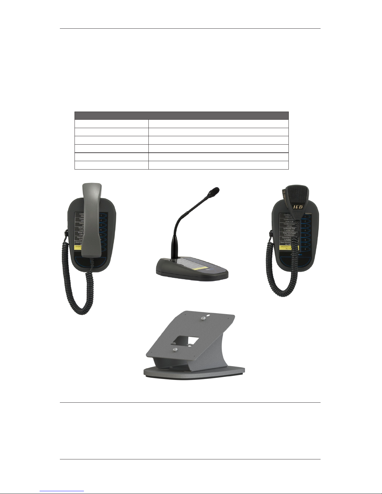
IEDA520D / LC108MS-D Desktop without microphone
IEDA520D-G / LC108MSD-G Desktop with gooseneck microphone
IEDA520W Wall-mount without microphone
IEDA520W-T / LC108MSW-HS Wall-mount with telephone handset microphone
IEDA520W-H / LC108MSW-HH Wall-mount with hand-held microphone
IEDA520DTB Optional desktop mounting base for W models
Network Requirements
The IED 520 Series Digital Communication Stations utilize CobraNet®technology licensed from Cirrus Logic®.
Live audio on the data network is time sensitive and requires minimal latency through the network to ensure unin-
terrupted audio. The IED 520 Digital Microphone Station and CobraNet operate on Layer 2 (MAC Layer) of the OSI
Model. This traffic will not operate on a Layer 3 Router or above. VLAN’s (Virtual Local Area Networks) may be re-
quired for managing traffic as well as Quality of Service (QoS) and Prioritization configuration of network switches.
All connections to the 520 Digital Microphone Stations must be full duplex 100 Mbps Ethernet auto-negotiation.
IEDA520W-T
LC108MSW-HS
IEDA520DTB
Desktop Base
IEDA520W-H
LC108MSW-HH
IEDA520D-G
LC108MSD-G
REV: 01-12 DOC: 369B PAGE 3
INSTALLATION INSTRUCTIONS IEDA520 / LC108 DIGITAL COMMUNICATION STATION
IMPORTANT SAFETY INSTRUCTIONS
1. Read these instructions.
2. Keep these instructions.
3. Heed all warnings.
4. Follow all instructions.
5. Do not use this apparatus near water.
6. Clean only with dry cloth.
7. Install in accordance with the manufacturer’s in-
structions.
8. Do not install near any heat sources such as ra-
diators, heat registers, stoves, or other apparatus
(including amplifiers) that produce heat.
9. Only use attachments/accessories specified by the
manufacturer.
10. Refer all servicing to qualified service personnel.
Servicing is required when the apparatus has been
damaged in any way, such as power-supply cord
or plug is damaged, liquid has been spilled or ob-
jects have fallen into the apparatus, the apparatus
has been exposed to rain or moisture, does not
operate normally, or has been dropped.
SAFETY SYMBOLS
Labeling on products and the Installation Instructions &
User Manual may use safety related graphical symbols
as shown below to note safety requirements.
Lightning Bolt: The lightning flash with
arrowhead symbol, within an equilateral triangle,
WARNING symbol, is intended to alert the user to
the presence of un-insulated dangerous voltage
within the product’s enclosure that may be
sufficient in magnitude to constitute a risk of
electric shock to persons or domestic animals.
Exclamation Point: The exclamation point
within an equilateral triangle, CAUTION symbol,
is in-tended to alert the user to the presence of
important operating and maintenance (servicing)
instructions, or a hazard that can damage equip-
ment.
Do not proceed beyond a WARNING or CAUTION notice
until you have understood the hazardous condition and
have taken appropriate steps.
SPECIFICATIONS
Electrical Frequency Response ...............................................................................+0, –1.0 dB
22 Hz - 22 kHz, Input Level = –20 dBu
Total Harmonic Distortion, THD ....................................................................... <0.1%
–20 dBu input, 22 Hz - 22 kHz
Signal-to-Noise Ratio, S/N .............................................................................. >85 dB
22 Hz - 22 kHz, –20 dBu Input
Analog-to-Digital Converter, A/D ......................................................................... 24 bit
Internal Processing .................................................................... 32 bit, Floating Point
Sample Rate .....................................................................................................48 kHz
Latency (Through < 7 network switch hops) .............................................. 5.7 mSec
Mechanical Desktop Size.........................................................5.25” x 8.18” x 1.58” high (at back)
Wall Mount Size.....................................5.41” x 8.29” x 1.74” deep (at thickest point)
Wall Mount mounting .........................................................Keyhole slots for standard
1-gang electrical box
Standards Utilized Full-Duplex Operations ........................................................................... IEEE 802.3x
Fast Ethernet, 100Mbps .......................................................................... IEEE 802.3u
The 520 Series specifically uses 100Base-TX
Data Terminal Equipment Power ........................................................... IEEE 802.3af
via Media Dependent Interface (PoE) with 3-GC cover
Connecting Cable Digital Audio/Power/Control ............................................................. CAT5e or better
For distances to a maximum of 100 Meters (approximately 300 feet) to the con-
nected switch. Cable installed and tested in accordance with ANSI/TIA/EIA 568B
Standards.
Environmental Operating Temperature Range ............................ +32˚Fto+104˚F(0˚Cto+40˚C)
Storage Temperature Range .............................–40˚F to +158˚F (–40˚C to +70˚C)
Power
Consumption
Supply Power .....................................................................................................<10W
Supply Voltage = 48VDC
PAGE 4DOC: 369B REV: 01-12
IEDA520 / LC108 DIGITAL COMMUNICATION STATION INSTALLATION INSTRUCTIONS
CONNECTIONS
IEDA520D / LC108MS-D Base Unit
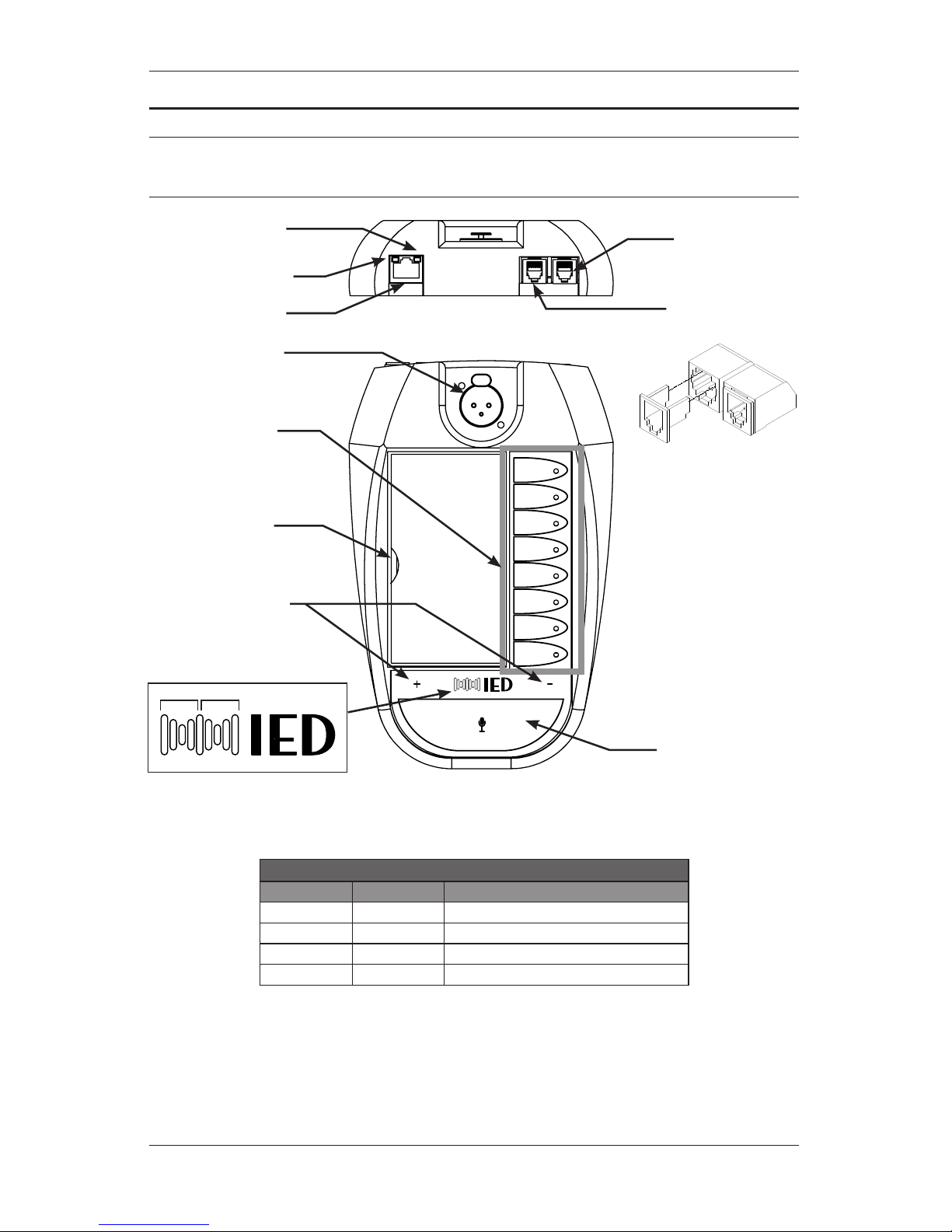
The desktop base unit contains
two (2) RJ11 (6P6C) jacks that
allow compatibility with IED
microphone cords and other
equipment that utilizes RJ11
connectors. Many telephone
handset and headset inter-
faces use smaller RJ9 (4P4C
or 4P2C) plugs. The unit is
supplied with slide-in adapters
to allow for a better fit when us-
ing the smaller handset plugs.
These must be removed when
using the larger RJ11 (6P6C)
plugs.
1
2
3
4
5
6
7
8
1
2
3
4
5
6
7
8
RED
GREEN
Status LEDs are integrated into the logo
Handset/Headset
Input
RJ45 Ethernet
Telephone Pass-
Through
XLR for Gooseneck mic
Pin 1 = S
Pin 2 = +
Pin 3 = –
Slot for button
label card
Announcement
selection buttons
with status LEDs
Traffic LED
Flashes green with network
activity
Status LED
Solid amber indicates
100BaseT link
Intercom volume
control buttons
Hold together for 3 seconds to
enter setup mode
Status LEDs
ANNOUNCE Button
Configured either as a push-to-
talk or toggle button
** A reset button is available through a small hole
located on the bottom of the unit
LED Indicators
RED GREEN MEANING
Solid Solid Waiting for Host
Off Fast Blink Ready to make an announcement
Off Solid Announce in progress (while holding PTT)
Fast Blink Off System busy or announce request invalid
REV: 01-12 DOC: 369B PAGE 5
INSTALLATION INSTRUCTIONS IEDA520 / LC108 DIGITAL COMMUNICATION STATION
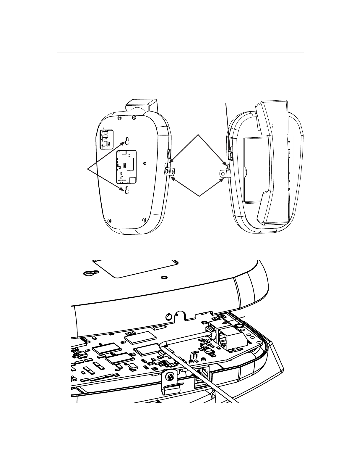
IEDA520W-H / LC108MSW-HH
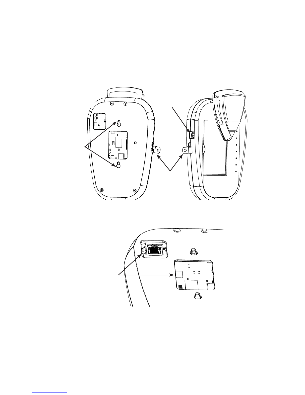
The front panel controls between the desktop and wall-mount base units are identical. This illustration highlights the
connection differences between the two units. Note that the telephone handset/headset interface is only available in the
desktop base units and not in the wall-mount units.
Route microphone
cord through this
strain relief and secure
with the included
screw.
Use RJ11 jack for
501HH microphone
only. The 520HS
handset will not work
in this jack.
Keyholes for
mounting unit
to a standard
1-gang electrical
box
Route ethernet
cable through
the access open-
ings to the RJ45
ethernet jack.
PAGE 6DOC: 369B REV: 01-12
IEDA520 / LC108 DIGITAL COMMUNICATION STATION INSTALLATION INSTRUCTIONS
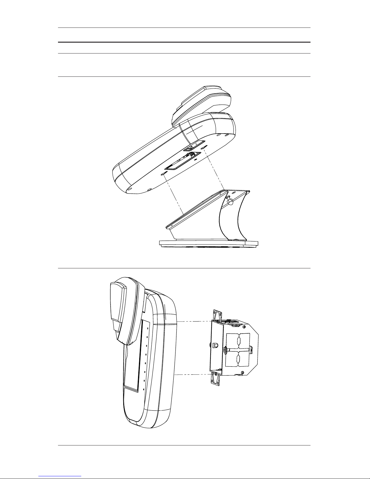
IEDA520W-T / LC108MSW-HS
The IEDA520HS handset has a different output signal level from the IEDA501HH. Thus, it must be connected a dedicated
handset input located inside the unit. Due to this difference, the IEDA520HS ships attached to the base unit.
Route microphone
cord through this
strain relief and secure
with the included
screw.
Microphone cord
passes through this
hole to the handset
connector located
inside the unit
RJ11 connector is not
compatible with the
handset
Keyholes for
mounting unit
to a standard
1-gang electrical
box
Internal Handset
Cable Connection
REV: 01-12 DOC: 369B PAGE 7
INSTALLATION INSTRUCTIONS IEDA520 / LC108 DIGITAL COMMUNICATION STATION
INSTALLATION
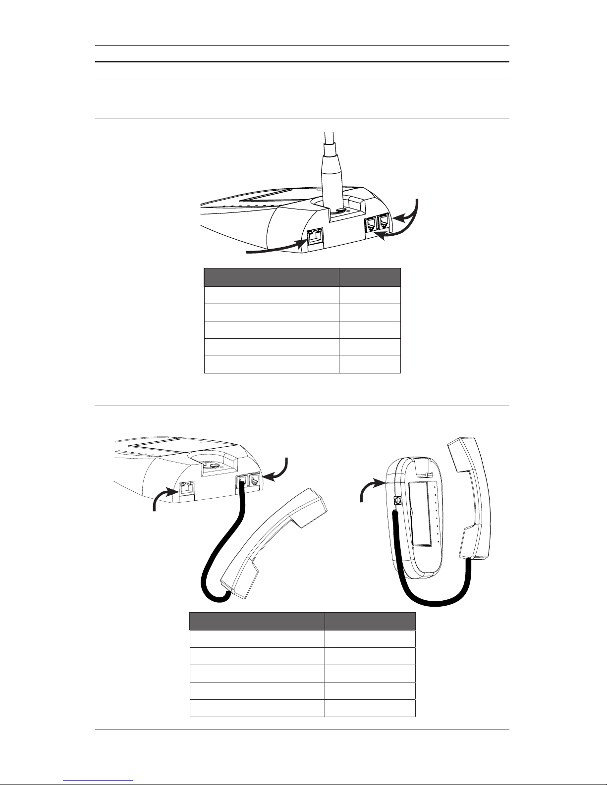
IEDA520W Base Unit Attached to IEDA520DTB Desktop Base
IEDA520DTB
IEDA520W Base Unit Attached to Standard Electrical Box
Standard 1-gang
electrical box
PAGE 8DOC: 369B REV: 01-12
IEDA520 / LC108 DIGITAL COMMUNICATION STATION INSTALLATION INSTRUCTIONS
CONFIGURATION EXAMPLES
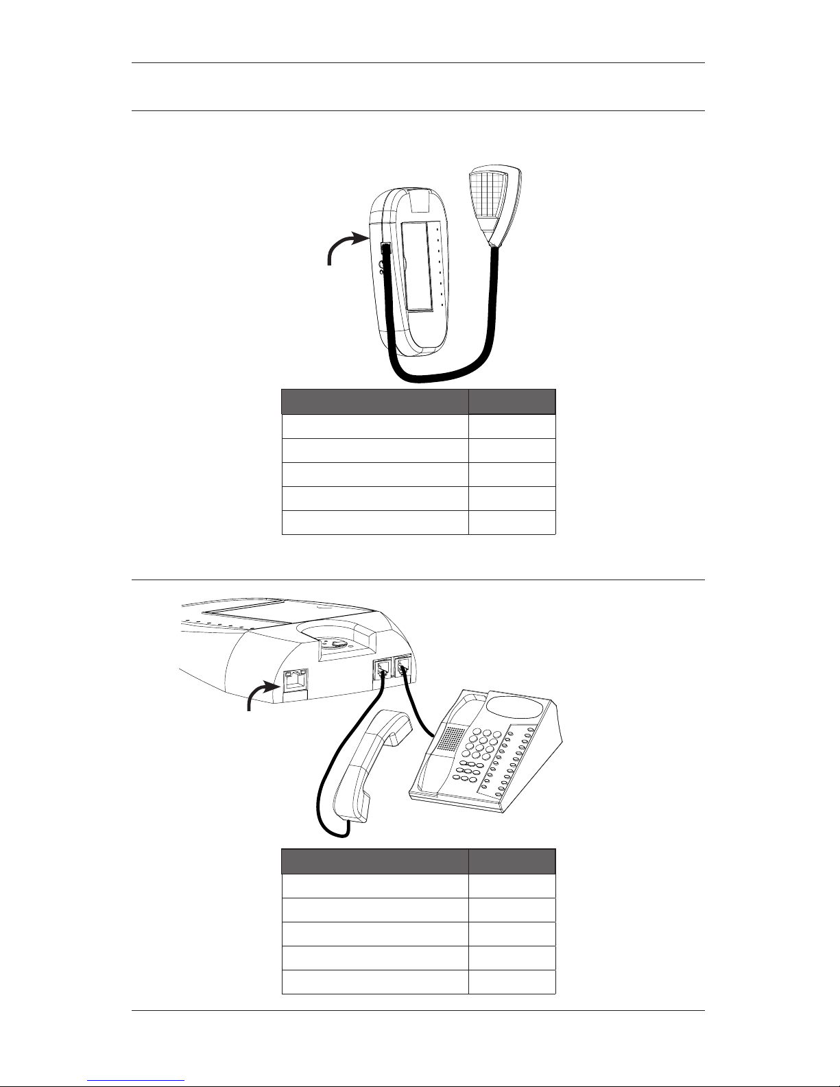
Configuration for Dynamic Gooseneck Microphone
PoE Ethernet
to port
No Connection
IEDA520D / LC108MSD Base
Parameter Setting
Mic Type Gooseneck
Gooseneck/Handset 20dB boost ON
Enable Telephone Passthrough N/A
Enable Sidetone N/A
Hand/Headset Power N/A
Configuration using IEDA520HS (no telephone)
IEDA520W / LC108MSW Base
PoE Ethernet
to port on back
of unit
PoE Ethernet
to port
No Connection
IEDA520D / LC108MSD Base
Parameter Setting
Mic Type Hand/headset
Gooseneck/Handset 20dB boost OFF
Enable Telephone Passthrough OFF
Enable Sidetone ON or OFF as desired
Hand/Headset Power ON
REV: 01-12 DOC: 369B PAGE 9
INSTALLATION INSTRUCTIONS IEDA520 / LC108 DIGITAL COMMUNICATION STATION
Configuration using IEDA501HH Hand-Held microphone
IEDA520W / LC108MSW
Base Only
PoE Ethernet
to port on back
of unit
Parameter Setting
Mic Type Handheld
Gooseneck/Handset 20dB boost OFF
Enable Telephone Passthrough N/A
Enable Sidetone N/A
Hand/Headset Power N/A
Configuration using telephone handset and telephone base
PoE Ethernet
to port
IEDA520D / LC108MSD Base Only
Parameter Setting
Mic Type Hand/headset
Gooseneck/Handset 20dB boost ON
Enable Telephone Passthrough ON
Enable Sidetone OFF
Hand/Headset Power OFF
Dieses Handbuch passt für folgende Modelle
1
Inhaltsverzeichnis


