Ikelite DS51 Bedienungsanleitung

Digital
Strobe
DS51
4044.1
Thank you for your purchase of kelite equipment. Please read this instruction manual
completely before attempting to operate or dive with this product. Please refer to the
back page of this manual to register your kelite product.

2
TABLE F C NTENTS
IKELITE DS51 DIG. STR BE ........3, 4
DS51 Specifications ........................3
ntroduction ......................................4
DS51 Strobe Use ............................4
Overview of DS51 Features ............4
Starting Out......................................4
M UNTING THE STR BE ............5
kelite Arm/Mounting Systems..........5
LITE BRACKET 4073......................5
STR BE C NNECTI N ................6
Connection to Strobe ......................6, 7
TTL/Sync Cords ..............................7
USING AS A TTL HARD-WIRED
STR BE ..........................................8
USING AS A HARD-WIRED STR BE
WITH UT TTL ................................9
USING AS A SLAVE STR BE........9, 10
BATTERY C MPARTMENT ..........11
Opening the Compartment ..............11
Battery Compartment O-ring............11
Changing the Batteries ....................11
Closing the Compartment ................12
Compartment Flooding ....................12
STR BE DIFFUSER ......................13
Using the Diffuser ............................13
Diffuser nstallation and Removal ....13
STR BE READY LIGHT ................14
Camera Ready Light ........................14
M DE SWITCH ..............................15
Off Position ......................................15
TTL/auto Exposure Position ............15
Manual Exposure Position ..............15
M DE SWITCH ILLUSTRATI NS..16
REC MMENDATI NS....................17
Visual nspections ............................17
nsurance ........................................17
Tips ..................................................17
Lubricant ..........................................17
MAINTENANCE ..............................18
Cleaning and Storage ......................18
TR UBLESH TING ....................19
Strobe Will Not Fire..........................19
PR DUCT REGISTRATI N ..........20
WARRANTY ....................................20
RETURNING PR DUCTS F R
SERVICE ........................................20

3
Bulkhead
Connector
(waterproof cap
removed)
51
ikelite
SUBSTROBE
DS
Bulkhead Cap
IKELITE DS51 STR BE
DS51 SPECIFICATI NS
Weight ....................................................0.6kg (1.3 lbs.) with batteries
Energy Rating ........................................50 watt-sec.
Coverage Angle ....................................70° (80° with diffuser)
Widest Angle Lens ................................28mm SLR
Guide Number ( SO 100) feet ...............56 surface, 28 underwater
Guide Number ( SO 100) meters ..........17 surface, 9 underwater
Firing Modes ..........................................TTL/Auto, Full, 5 fractional powers
Color Temperature 5700°K
Power Source ........................................4 AA-cell alkaline, NiCad, or NiMH
Flashes ..................................................200 full power
Recycle Time..........................................3.5 seconds (full power)
Depth Rating ..........................................90m (300 feet)
CE - Compliant with applicable EU directives
Complies with FCC part 15, subpart B, Section 15.109 for Class “B” Products
Caution:
- The DS51 bulkhead connector is not waterproof and must be capped when not
connected to a cord or sensor. Using a DS51 underwater with the bulkhead
connector uncapped or unconnected will cause the strobe to flood. Do not
continue to use a flooded strobe: return to kelite for repair.
- The strobe is factory sealed; do not disassemble. Disassembly will void your
kelite DS51 limited warranty.
- Do not continuously fire the strobe more than 15 times above water in rapid
succession. f this does happen, allow the strobe to cool down for at least 10
minutes.
Strobe
Ready
Light
Mode Switch
Waterproof
Bulkhead
Cap
Battery Door
Knob

4
INTR DUCTI N
Thank you for purchasing an kelite Strobe. kelite brings over 45 years of underwater
photographic and lighting experience to the strobe market. kelite Strobes are designed
and built in the USA by kelite to suit both the professional and the amateur photographer.
DS51 Strobe USE
The purpose of a strobe is to illuminate the subject and assist the camera in taking vivid
pictures. The kelite DS51 strobe is equally suited for general and wide-angle
photography, covering up to 80° with a diffuser. The compact size of the DS51 makes it
ideal for macro photography while its 5700°K color temperature helps bring out the true
colors of the underwater world.
The kelite DS51 strobe is pre-flash compatible and operates with traditional film
cameras, DSLR cameras, and digital still cameras. TTL/auto and manual exposure with
five fractional power setting firing modes are featured. The DS51 electronics are safely
sealed away from the battery compartment.
Aim the DS51 strobe and illuminate your subject’s colors with the optional Mini-C Lite and
Lite Bracket 4073 (page 5). The bracket secures beneath the strobe, allowing the Mini-C
Lite to be used as both an aiming light and as a night diving light.
VERVIEW F DS51 FEATURES
- Mode switch features TTL/auto and manual exposure settings.
- Battery compartment accommodates four AA batteries: alkaline, NiCad, or NiMH.
Lithium-ion batteries are NOT recommended.
- Ready light indicates when strobe has recycled.
- Female kelite bulkhead connector accepts different camera sync cords and the
4403 Optical Slave Converter.
- Exposure guide label references recommended exposure settings.
- Diffuser provides softer lighting, wider coverage angle and reduces strobe output
by one f-stop.
STARTING UT
Before using the kelite DS51 Strobe, please read this owner’s manual thoroughly and
retain it for future reference. kelite recommends becoming familiar with the features and
functions of the kelite DS51 Strobe above water before trying the camera and strobe in
the water. And, if you have not yet done so, it is suggested that you read your camera’s
owner’s manual as well.
IKELITE DS51 STR BE

51
ikelite
SUBSTROBE
DS
5
IKELITE ARM/M UNTING SYSTEMS
kelite offers several arm choices compatible
with the DS51. Arms and mounts are NOT
supplied with the strobe unless purchased as
part of a complete package.
The DS51 will accept several kelite strobe
arms and mounts on the underside of the
strobe body. For further information, please
visit www.ikelite.com.
Caution: kelite arm systems are designed for
underwater use. Be careful when transporting
the system above water since some camera
trays, or arm adjustments may be unable to
support the weight of the strobe(s) above
water.
M UNTING THE STR BE
Lite Bracket 4073
The optional Lite Bracket secures the
kelite Mini-C Lite underneath the
DS51 strobe for use as an aiming light
and night diving light.
The Lite Bracket is placed between
the strobe body and the strobe mount.
Using a Phillips Head screwdriver,
remove the strobe mount from the
underside of the strobe and secure the
Lite Bracket in its place. Then, using
the extra screw provided with the
Lite Bracket, secure the strobe mount
under the bracket.
Lite Bracket for
Mini C-Lite
51
ikelite
SUBSTROBE
DS
Screw
4080.01 1-inch Ball
Arm System Mark

6
The female kelite bulkhead connector permits kelite sync cords to be connected to the
strobe. The sync cord relays a signal from the camera to the strobe that tells the DS51 when
to flash.
The removable waterproof bulkhead cap seals the bulkhead connector when a cord is
connected to the DS51. The strobe’s bulkhead connector must be sealed to remain
waterproof (page 7).
Caution:
- Do not leave the sync cord connected to the camera housing or strobe
for prolonged periods as electrolysis could occur and make removal of the
equipment impossible.
- Do not disconnect the sync cord from the camera housing or strobe when
underwater, or when wet. These items are not waterproof when disconnected.
C NNECTI N T STR BE
To connect a sync cord to the DS51 Strobe, follow these instructions:
1. Turn the strobe to OFF and make sure all components are dry. Clean and
lightly lubricate the stem o-ring and the bulkhead connector threads.
Check the o-ring for nicks or cuts.
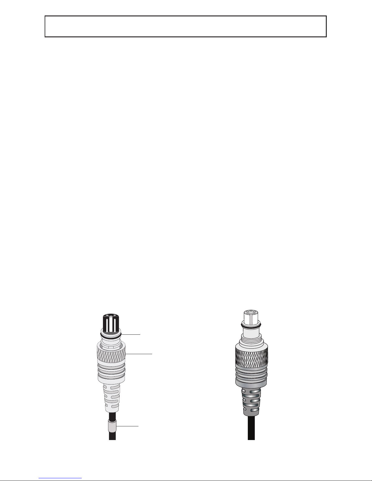
2. Note the positioning of the receptacles and pins on the end of the cord. Properly
align the end of the cord and insert it into the strobe bulkhead connector.
When using the 4103.51 cord, which connects an kelite housing to an kelite
strobe, both cord ends are identical; either end can be connected to the
strobe.
3. The connector threads are very fine; do not cross thread. f it is difficult
to turn the knurled retaining ring on the cord or sensor, you are cross-threading.
This can make removal of the strobe impossible.
Hand-tighten the knurled retaining ring on the cord. Push the end of
the cord further into the bulkhead connector and continue to tighten the knurled
retaining ring. Do not use a tool when tightening. t could damage the
cord or strobe.
STR BE C NNECTI N

7
Bulkhead
Connector
(waterproof cap
removed)
51
ikelite
SUBSTROBE
DS
Bulkhead Cap
Retaining
Ring
Stem O-ring
Blue
Band
STR BE C NNECTI N continued
kelite Sync Cord
TTL SYNC C RDS
kelite offers interchangeable sync cords so that the DS51 strobe can be connected to
different camera systems. A TTL sync cord (illustrated above) is required to send the
TTL/auto exposure signal from the camera to the strobe.

8
For use with the following types of systems:
- kelite housings for digital cameras with TTL conversion circuitry
- kelite housings for film cameras
- Nikonos V, RS cameras
- Non- kelite housings for digital cameras and compatible TTL adapter
Connect the strobe using an appropriate kelite TTL sync cord. Digital cameras require the
use of a Digital TTL sync cord. These cords are designated by a blue band at one end.
The DS51 may be used in TTL/auto or manual exposure modes.
TTL (thru-the-lens) exposure automatically compensates for aperture, distance and filters.
When the strobe fires, the camera reads the light and signals the strobe to turn off when
the exposure is correct.
Strobe output can be adjusted in TTL/auto mode using either exposure compensation built
into the camera or an exposure compensation control (dial or push buttons) located on the
back of the housing (if applicable).
f an exposure compensation control is featured in the back of the housing, strobe output
may be controlled manually while the strobe itself is left in TTL/auto mode. n order to use
the manual exposure modes on the strobe itself, the housing electronics must be set to a
manual position.
When using a non- kelite TTL adapter or third party conversion circuitry, please refer to
the product instructions for help in using the DS51 with this setup.
USING AS A TTL HARD-WIRED STR BE
Retaining
Ring
Stem O-ring
Blue
Band
kelite Sync Cord Nikonos Sync Cord

9
For use with the following types of systems:
- kelite housings for digital cameras with external strobe connector but without
TTL conversion circuitry
- Non- kelite housings for digital cameras with Nikonos-style strobe connector
Connect the strobe using an appropriate kelite sync cord. The DS51 must be used in
manual exposure modes. Strobe output is not automatically adjusted for proper exposure
when set to TTL/auto mode.
USING AS A HARD-WIRED STR BE WITH UT TTL
USING AS A SLAVE STR BE - Diagram A, Page 10
Trigger your kelite DS-series strobe off any camera or strobe flash. The Optional 4403
Optical Slave Converter simply attaches to the strobe's electrical bulkhead in place of a
sync cord connector. The enlarged slave window provides approximately a 90 degree
field of view for remote triggering; or you can thread on the Fiber Optic Port (included
with Slave Converter) for the attachment of and triggering with a fiber optic cord.
The Optical Slave Converter automatically configures itself for compatibility with both
pre-flash and non pre-flash camera modes. No setting of small switches or confusion
over number of pre-flashes. Simply turn on your strobe and take one picture to configure.
The Optical Slave Converter can be extended using an optional 3-foot Extension Cord
for creative backlighting in wrecks, caves, and pool studio set-ups. t can also be used
above water for studio photography work.
The Optical Slave Converter supports manual exposure modes as set on the attached
DS strobe. TTL exposure mode is not supported.
Use of multiple strobes requires one Optical Slave Converter per strobe.
The Converter can be triggered off a camera flash or another strobe.

51
ikelite
SUBSTROBE
DS
10
DS-51 Strobe Bulkhead
Plug Lock Retainer
O-ring, O-ring Sealing Groove
Plug Attachment Point for
kelite, SEA&SEA-type and
Olympus cables
4403 Optical
Slave Converter
Threaded Fiber Optic Port
Attachment 0314.4
Diagram A
USING AS A SLAVE STR BE - continued
Andere Handbücher für DS51
3
Inhaltsverzeichnis
Andere Ikelite Kamerablitz Handbücher