
Imron Corporation MR-DT Bedienungsanleitung
Imron Corporation
15375 Barranca Pkwy, Suite B-106
Irvine, CA 92618
Phone 949-341-0947
Fax 949-341-0949
INTEGRATED SYSTEM 2000 MR-DT DISPLAY TERMINAL
Installation and Specification
1. General:
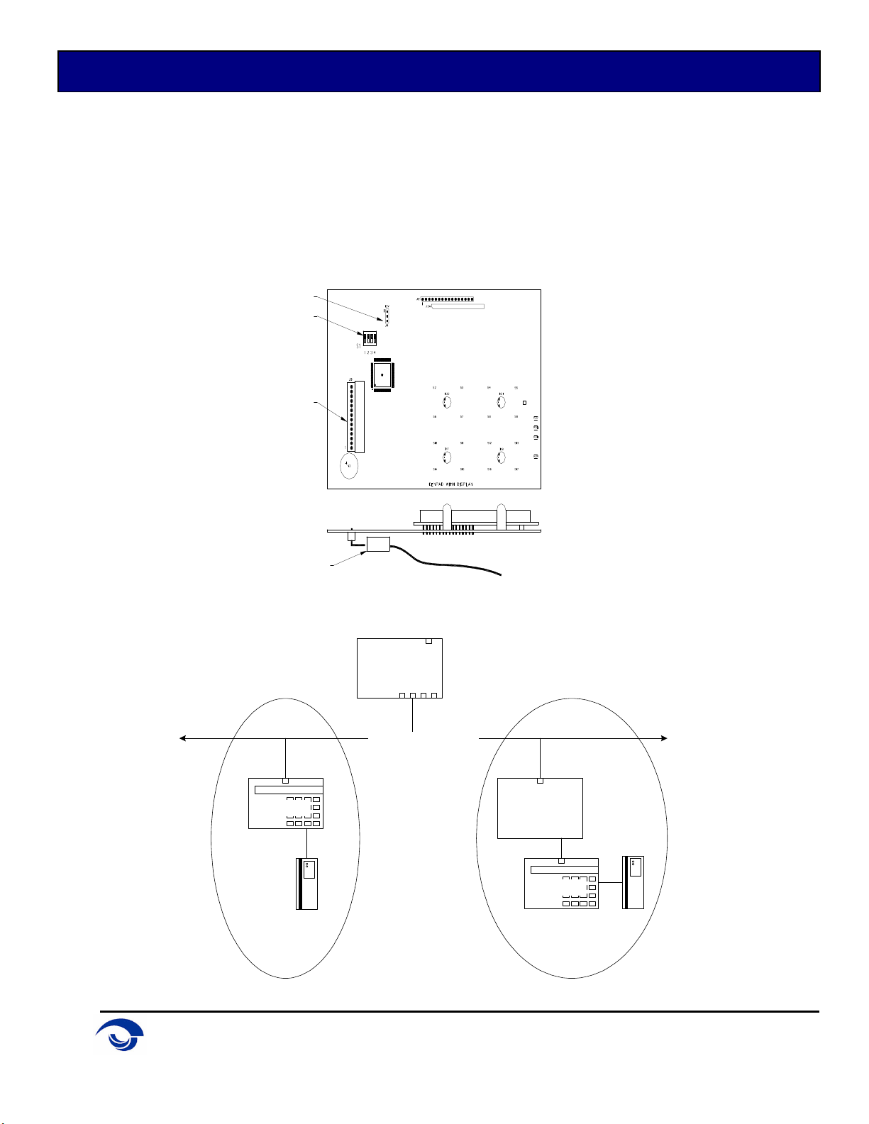
The MR-DT integrates a 2 line x 16 character back-lit LCD display with a 16-position keypad and a reader
port. This highly functional I/O device can communicate to the system controller via a 2-wire RS-485
interface. It can also communicate to an MR-52 reader interface with a TTL interface.
COMPONENTLOCATION
FLASHVOLTAGE
DIPSWITCH
INTERFACECONN
INTERFACECABLE
Processor
MR-52
MR-DT
MR-DT
2-WireRS-485 Serial Bus
Via RS-485... Via Reader Port...
Imron Corporation
15375 Barranca Pkwy, Suite B-106
Irvine, CA 92618
Phone 949-341-0947
Fax 949-341-0949
INTEGRATED SYSTEM 2000 MR-DT DISPLAY TERMINAL
2. Wiring:
The MR-DT requires 12Vdc ±15% for power and the power source must be filtered.
The terminal communicates to a controller via a half duplex multi-drop 2-wire RS-485 interface. The total
cable length is limited to 4,000 feet (1,200 meters). Shielded cable of 24AWG with characteristic
impedance of 120 ohm is specified for the RS-485 interface. The last device on each end of the cable
should have the termination installed (set jumper DIP1=ON).
Alternatively, the terminal may communicate with a reader interface (MR-52) within a limited distance of
500 feet (152 meters) using an 18AWG cable.
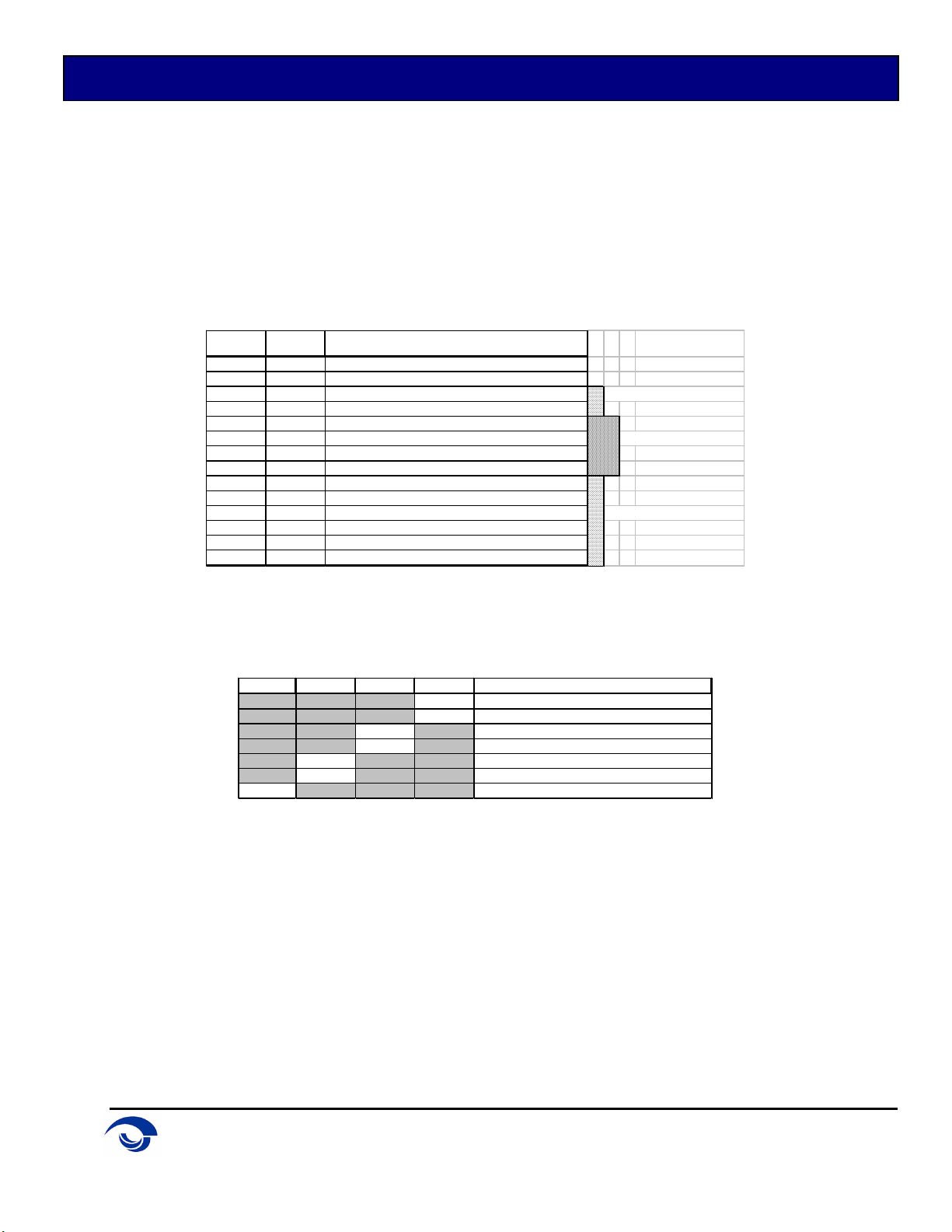
J3 Color SIGNAL
1 RED 12Vdc IN
2 BLK GROUND
3 BLU RS-485 TR+ ---RS-485 connection
4 GRY RS-485 TR-
5 GRN TTL DATA, connect to MR-52 DATA 0
6 WHT TTL DATA, connect to MR-52 DATA 1 ---MR-52 connection
7 BRN TTL DATA, connect to MR-52 LED
8 ORG TTL DATA, connect to MR-52 BZR
9 RED 12Vdc PASS THROUGH FOR READER
10 GRN READER DATA (or DATA 0)
11 WHT READER CLOCK (or DATA 1) ---Reader Port
12 BRN READER LED
13 ORG READER BUZZER
14 BLK GROUND
3. CONFIGURATION:
Hardware Configuration
DIP4 DIP3 DIP2 DIP1 SELECTION
OFF RS-485 - No Termination
ON RS-485 - 120 Ohm Termination
OFF Use Configuration Settings
ON Forces 38400 baud & addr 31
OFF Allow software configuration at startup
ON Disble software configuration at startup
OFF NOT USED
DIP1: Proper termination practices must be followed to insure proper operation. If the MR-DT is the
last device on the RS-485 bus, termination should be set to ON.
DIP2: Used for testing. This DIP forces the baud rate and address to a known value.
DIP3: When set to ON, this disables the ability to use the keypad for changing the configuration.
This decreases the possibility of unauthorized persons from altering the configuration.
DIP4: Not used.
Jumpers
J1 Factory use only. Always open.
J4 Close pins 1-2 to allow flash upgrade of firmware. Open to disable.

Imron Corporation
15375 Barranca Pkwy, Suite B-106
Irvine, CA 92618
Phone 949-341-0947
Fax 949-341-0949
INTEGRATED SYSTEM 2000 MR-DT DISPLAY TERMINAL
Software Configuration
Configuration of the MR-DT is performed at the keypad during the startup process. When power is
applied, the screen will flash a message: "Press two keys for Setup." If the two keys are pressed
simultaneously, the setup screen will appear. The following list describes each setting:
COMM: The MR-DT can be connected to the system via two possible interfaces.
RS-485=Connects to SCP via 2-wire RS-485 channel.
Reader Port=Connects to an MR-52 reader port.
Baud rate (if RS-485): This selection should match with the baud rate of the processor.
Comm Address (if RS-485): The comm address should be set to a unique value for the RS-485 bus.
The valid range is 0-31.
Backlight: This setting defines the behavior of the display's backlight.
00=always off
99=always on
01-98=number of seconds the backlight remains on after last keystroke.
LED: Selects the LED drive type to match the reader connected to the reader
port.
1-Wire: standard 1-wire interface (High=RED, Low=GREEN)
2-Wire: BRN wire controls Red LED (High=Off, Low=On)
ORG wire controls Green LED (High=Off, Low=On)
(No Buzzer)
Once all configuration items are entered via the display, the configuration must be saved. If a mistake is
made, answering NO to "save settings" will return you to the first screen of the configuration menu.
4. Status Display:
The MR-DT can display a status report which allows the user to confirm the settings, read back the serial
number, firmware revision number, and hardware settings. It also displays communication status as on-
line or off-line.
5. Specification:
This device complies with part 15 of the FCC Rules. Operation is subject to the following two conditions:
(1) This device may not cause harmful interference, and (2) this device must accept any interference
received, including interference that may cause undesired operation.

Imron Corporation
15375 Barranca Pkwy, Suite B-106
Irvine, CA 92618
Phone 949-341-0947
Fax 949-341-0949
INTEGRATED SYSTEM 2000 MR-DT DISPLAY TERMINAL
Liability
The Interface should only be used to control exits from areas where an alternative method for exit is
available. This product is not intended for, nor is rated for operation in life-critical control applications.
Imron Corporation is not liable under any circumstances for loss or damage caused by or partially caused
by the misapplication or malfunction of the product. Imron Corporation's liability does not extend beyond
the purchase price of the product.
Inhaltsverzeichnis


