
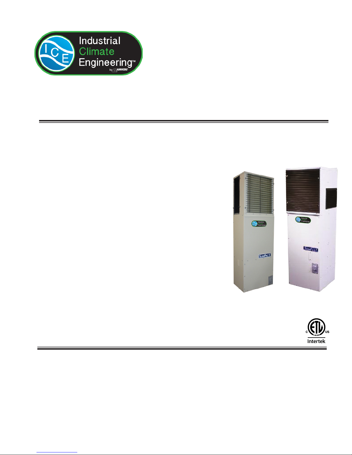
Industrial Climate Engineering SlimPac ECUA12 Bedienungsanleitung
ICE SlimPac ECUA12-18 I&O Manual 03/2019 Rev.2
Part Number 01706
Chapter 1 Description................................. 5
Chapter 2 Installation............................... 14
Chapter 3 Start-Up ................................... 20
Chapter 4 Troubleshooting ....................... 21
Chapter 5 Maintenance............................. 24
Chapter 6 Warranty .................................. 25
Chapter 7 Exploded View Parts List.......... 26
ECU Installation & Operation Manual
Vertical Air Conditioners
Models SlimPac ECUA12-18
Manufactured By:
Industrial Climate Engineering™ Division of AIRXCEL®, Inc.
P.O. Box 5104 • Cordele, Georgia 31010
2002 Hoover St. • Cordele, Georgia 31015
(229) 273-9558 • Fax (229) 273-5154
The most current version of this manual can be found at www.acice.com.
ECUA12 ECUA18
2
ICE SlimPac ECUA12-18 I&O Manual 03/2019 Rev.2
How To Use This Manual
This manual is intended to be a guide to Industrial Climate Engineering's line of vertical air conditioners. It contains
installation, troubleshooting, maintenance, warranty, and application information. The information contained in this
manual is to be used by the installer as a guide only. This manual does not supersede or circumvent any applicable
national or local codes.
If you are installing the air conditioner rst read Chapter 1 and scan the entire manual before beginning the installation as
described in Chapter 2. Chapter 1 contains general, descriptive information and provides an overview which can speed
up the installation process and simplify troubleshooting.
If a malfunction occurs, follow this troubleshooting sequence:
1. Make sure you understand how the air conditioner works (Chapters 1 & 3).
2. Identify and correct installation errors (Chapter 2).
3. Refer to the troubleshooting information in Chapter 4.
If you are still unable to correct the problem, contact the Factory at 1-229-273-9558 for additional assistance.
Please read the following “Important Safety Precautions” before beginning any work.
Important Safety Precautions
1. USE CARE when LIFTING or TRANSPORTING equipment.
2. TRANSPORT the UNIT UPRIGHT. Laying it down on its side may cause oil to leave the compressor and breakage
or damage to other components.
3. TURN ELECTRICAL POWER OFF AT THE breaker or fuse box BEFORE installing or working on the equipment.
LINE VOLTAGES ARE HAZARDOUS or LETHAL.
4. OBSERVE and COMPLY with ALL applicable PLUMBING, ELECTRICAL, and BUILDING CODES and ordi-
nances.
5. SERVICE may be performed ONLY by QUALIFIED and EXPERIENCED PERSONS.
* Wear safety goggles when servicing the refrigeration circuit
* Beware of hot surfaces on refrigerant circuit components
* Beware of sharp edges on sheet metal components
* Use care when recovering or adding refrigerant
6. Use COMMON SENSE - BE SAFETY-CONSCIOUS
This is the safety alert symbol . When you see this symbol on the air conditioning unit and in the instruction
manuals be alert to the potential for personal injury. Understand the signal word DANGER, WARNING and
CAUTION. These words are used to identify levels of the seriousness of the hazard.
DANGER Failure to comply will result in death or severe personal injury and/or property damage.
WARNING Failure to comply could result in death or severe personal injury and/or property damage.
CAUTION Failure to comply could result in minor personal injury and/or property damage.
IMPORTANT Used to point out helpful info that will result in improved installation, reliability or operation.
© 03/2019 Industrial Climate Engineering™ Div. Airxcel™, Inc.
SPECIFICATIONS SUBJECT TO CHANGE WITHOUT NOTICE.

3ICE SlimPac ECUA12-18 I&O Manual 03/2019 Rev.2
WARNING
• If the information in these instructions are not followed exactly, a re may result
causing property damage, personal injury or loss of life.
• Read all instructions carefully prior to beginning the installation. Do not begin
installation if you do not understand any of the instructions.
• Improper installation, adjustment, alteration, service or maintenance can cause
property damage, personal injury or loss of life.
• Installation and service must be performed by a qualied installer or service agency in
accordance with these instructions and in compliance with all codes and requirements
of authorities having jurisdiction.
INSTALLER: Afx the instructions on the inside of the building adjacent to the
thermostat.
END USER: Retain these instructions for future reference.
Table of Contents
Chapter 1 Air Conditioner Description & Specications
1.1 General Description .................................................................................................................................5
1.2 Model Identication .................................................................................................................................5
1.3 Serial Number Date Code ........................................................................................................................5
1.4 Electrical Data and Performance Data .....................................................................................................6
1.5 General Operation ....................................................................................................................................6
1.6 Electrical Diagrams..................................................................................................................................9
1.7 Electronic Control Board Mode of Operation........................................................................................12
Chapter 2 Installation
2.1 Equipment Inspection.............................................................................................................................14
2.2 Installation Requirements.......................................................................................................................14
2.3 Installation Materials ............................................................................................................................15
2.4 Porting and Duct Work ..........................................................................................................................16
2.5 Air Flow Requirements and Ducting ....................................................................................................16
2.6 Bottom Bracket Installation ...................................................................................................................17
2.7 Condenser Blower Orientation...............................................................................................................18
2.8 Mounting the Unit .................................................................................................................................18
2.9 Electrical Connections ...........................................................................................................................18
Chapter 3 Start-Up
3.1 Check-Out of Cooling Cycle .................................................................................................................20
3.2 Check-Out of Heating Cycle..................................................................................................................20
3.3 Check-Out of High Temp. Alarm and/or Gas Detection Device............................................................20
Chapter 4 Troubleshooting
4.1 Overview ................................................................................................................................................21
4.2 Failure Symptoms Guide........................................................................................................................21
4.3 Compressor Troubleshooting .................................................................................................................22

4
ICE SlimPac ECUA12-18 I&O Manual 03/2019 Rev.2
Table of Contents
Chapter 5 Maintenance
5.1 Scheduled Maintenance .........................................................................................................................24
Chapter 6 Warranty
6.1 Airxcel Commercial/Industrial Group Limited Product Warranty.........................................................25
Chapter 7 Start-Up Check List
7.1 Start-Up Check List................................................................................................................................26
Illustrations
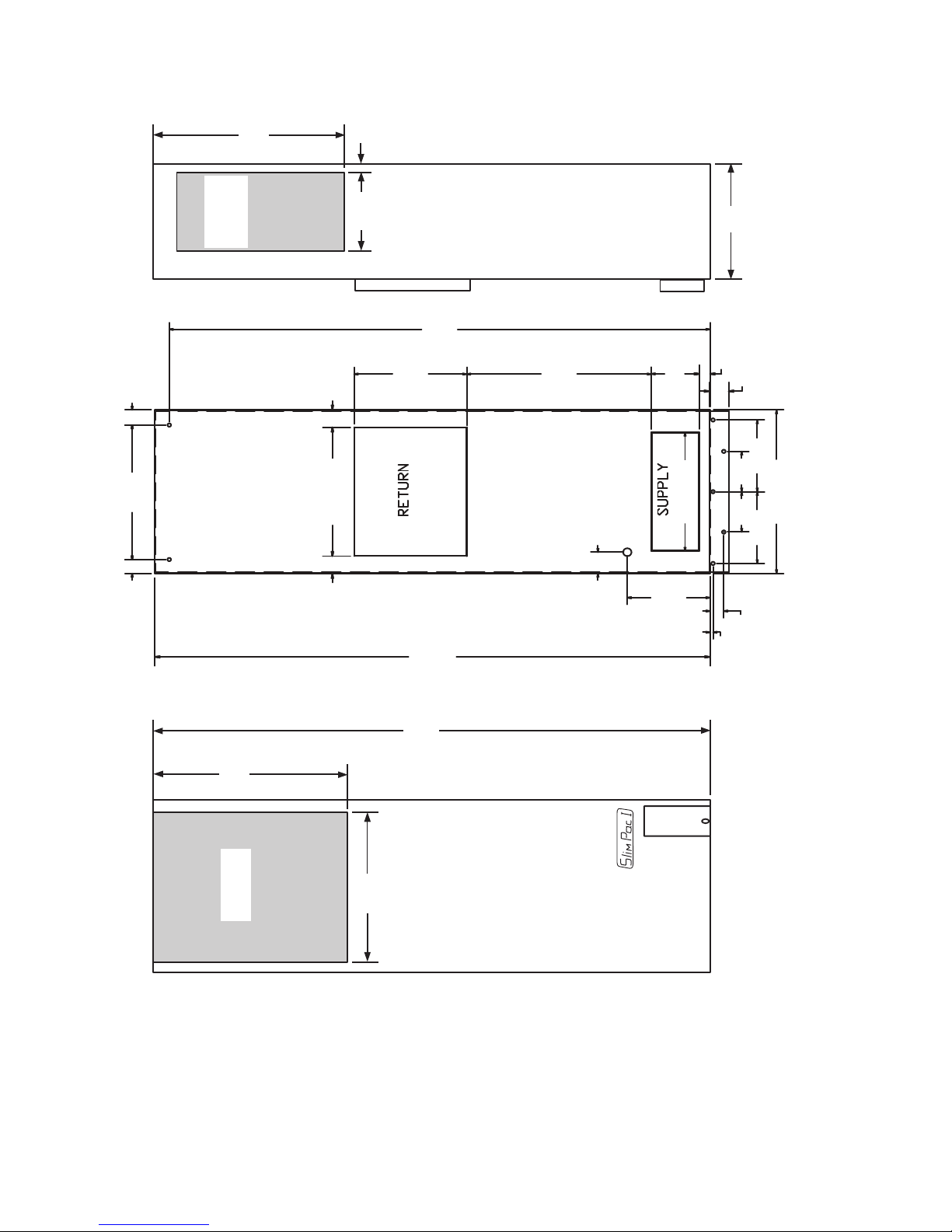
Figure 1a. Dimensional Data - ECUA12................................................................................................... 7
Figure 1b. Dimensional Data - ECUA18................................................................................................... 8
Figure 2a. Typical Electrical Schematic - ECUA12................................................................................ 10
Figure 2b. Typical Electrical Schematic - ECUA18................................................................................ 11
Figure 3. Control Board Detail .............................................................................................................. 13
Figure 4. Wall Mount Detail.................................................................................................................. 17
Figure 5. Thermostat Wiring Diagram .................................................................................................. 19
Tables
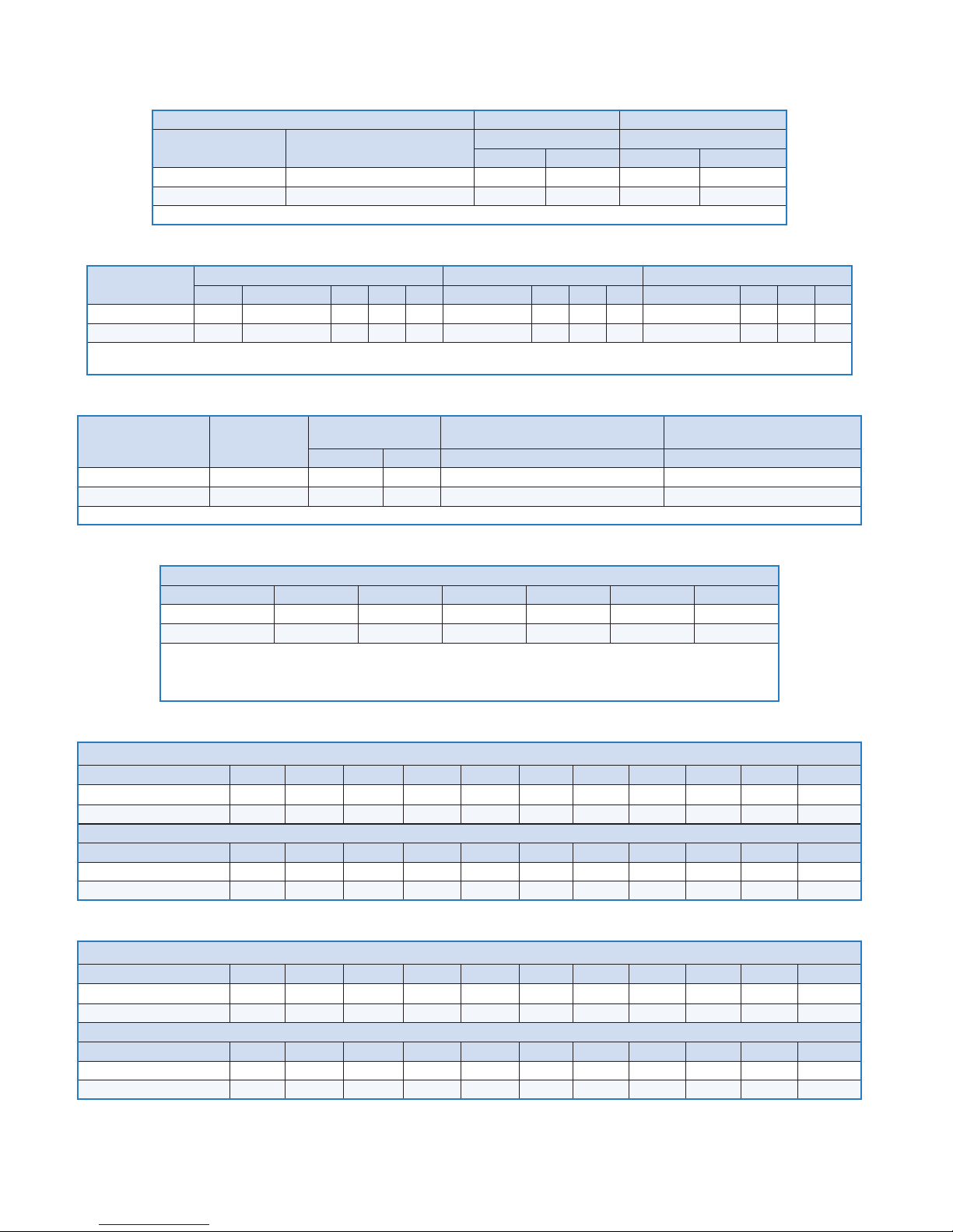
Table 1 Summary Ratings ..................................................................................................................... 6
Table 2 Electrical Characteristics.......................................................................................................... 6
Table 3 Unit Load Amps ....................................................................................................................... 6
Table 4 Air Flow ................................................................................................................................... 6
Table 5 ECUA12 Total & Sensible Cooling Capacity .......................................................................... 6
Table 6 ECUA18 Total & Sensible Cooling Capacity .......................................................................... 6
Table 7 Voltage Limitations ................................................................................................................ 15
Table 8 Maximum Static Pressure ...................................................................................................... 16

5ICE SlimPac ECUA12-18 I&O Manual 03/2019 Rev.2
Chapter 1 Description & Specications
1.1 General Description
The SlimPac™ line of environmental control units (ECUA) is designed for the telecommunication
cabinet and shelter. Below are some of the features of the unit.
• The SlimPac™ ECUA is available in cooling capacities of 12,000 BTUH (ECUA12) and 18,000
BTUH (ECUA18).
• Cabinet has powder coated nish for long term durability.
• ECUA protection provided by low refrigerant pressure switch (ECUA18 only), freeze stat and high
pressure switch.
• Dry contacts are available for remote monitoring of lockout due to a high or lower pressure.
• Low ambient operation provided by condenser fan cycle control (ECUA12) or modulating head
pressure control (ECUA18).
• 3.6 kW electric strip heat is optional.
• The ECUA12 and ECUA18 SlimPac are safety listed by ETL. Both units are manufactured and
tested to UL 1995 current edition and CAN/CSA-C22.2 No. 236 2nd Ed.
The operating functions of the SlimPac™ ECUA line are described below.
Cooling - Mechanical cooling is provided.
Heating - A 3.6 kW electric resistant heater (standard) operates to provide heating as required.
1.2 Model Identication
The model identication number is found on the data sticker. Rating plate located on side panel.
ECU A • AC A – 036
Electric Heat Designator = 3.6 kW
Voltage (A) = 208/230V, 1ø, 60 Hz
AC = Air Conditioner
Nominal Cooling Capacity (12) - 12,000 BTUH (18) = 18,000 BTUH
A = R-410A Refrigerant
(ECU) Environmental Control Unit
Example:
ECUA18ACA-036 = Counterflow Vertical Package ECU Nominal 1.5 tons; 208/230V, 1ø, 60 Hz; 3.6 kW Electric Heat
1.3 Serial Number Date Code
A = January E = May J = September D = 2014
B = February F = June K = October E = 2015
C = March G = July L = November F = 2016
D = April H = August M = December
6
ICE SlimPac ECUA12-18 I&O Manual 03/2019 Rev.2
1.4 Electrical Ratings and Performance Data
ELECTRIC HEAT 000 = None 036 = 3.6 kW
BASIC MODEL VOLTAGE / PHASE / HZ CKT #1 CKT #1
MCA MFS MCA MFS
ECUA12ACA (N) 208-230/1/60 9.3 15 19.7 20
ECUA18ACA (N) 208-230/1/60 14.9 20 20.4 25
MCA =Minimum Circuit Ampacity (Wire Sizing Amps) MFS = Max. Fuse Size or HACR circuit breaker
Table 1. Summary Ratings
BASIC MODEL COMPRESSOR OUTDOOR MOTOR INDOOR MOTOR
TYPE VOLTS-HZ-PH RLA LRA MCC VOLTS-HZ-PH RPM FLA HP VOLTS-HZ-PH RPM FLA HP
ECUA12ACA (N) Rotary 208/230-60-1 6.3 29.0 9.8 208/230-60-1 1050 0.50 1/15 208/230-60-1 1600 0.95 1/8
ECUA18ACA (N) Scroll 208/230-60-1 9.0 48.0 14.0 208/230-60-1 825 2.00 1/3 208/230-60-1 1075 1.60 1/4
RLA = Rated Load Amps LRA = Locked Rotor Amps MCC = Maximum Continuous Current RPM = Revolutions per Minute
FLA = Full Load Amps HP = Horsepower
Table 2. Electrical Characteristics
BASIC MODEL
NUMBER
VOLTAGE
HERTZ PHASE
CURRENT AMPS LOAD OF RESISTIVE HEATING
ELEMENTS ONLY (AMPS)
TOTAL MAXIMUM HEATING
AMPS (STANDARD UNIT)
AC UNIT IBM 3.6 kW 3.6 kW
ECUA12ACA (N) 208/230-60-1 7.75 0.95 15.00 15.95
ECUA18ACA (N) 208/230-60-1 12.60 1.60 15.00 16.60
IBM = Indoor Blower Motor
Table 3. Unit Load Amps
CFM @ ESP (Dry Coil)
Model .00 .05 .10 .15 .20 .25
ECUA12 510 470 450 420 390 360
ECUA18 750 710 680 650 625 600
CFM = Cubic Feet/Minute Indoor Air Flow
ESP = External Static Pressure in Inches WG
Note: Follow local codes and standards when designing duct runs to deliver the required airflow. Minimize noise
and excessive pressure drops caused by duct aspect ratio changes, bends, dampers and outlet grilles in duct runs.
Table 4. Air Flow
Data based upon 80°F Dry Bulb/ 67°F wet bulb return air temperature at Various Outdoor Temperatures. Airflow at 450 CFM
Outdoor temperature 70°F 75°F 80°F 85°F 90°F 95°F 100°F 105°F 110°F 115° 120°F
Total cooling (BTUH) 10,570 10,370 10,170 9,975 9,788 9,600 9,165 8,730 8,105 7,480 6,860
Sensible Cooling (BTUH) 6,930 6,860 6,790 6,720 6,655 6,590 6,435 6,280 6,065 5,850 5,640
Data based upon 26.5°C Dry Bulb/ 19.5°C wet bulb return air temperature at Various Outdoor Temperatures. Airflow at 760 m3/hr.
Outdoor temperature 21°C 24°C 26.5°C 29°C 32°C 35°C 38°C 40.5°C 43.3°C 46° 48.4°C
Total cooling (kW) 3.10 3.04 2.98 2.92 2.87 2.81 2.69 2.56 2.37 2.19 2.01
Sensible Cooling (kW) 2.03 2.01 1.99 1.97 1.95 1.93 1.89 1.84 1.78 1.71 1.65
Table 5. ECUA12 Total & Sensible Cooling Capacity
Data based upon 80°F Dry Bulb/ 67°F wet bulb return air temperature at Various Outdoor Temperatures. Airflow at 500 CFM
Outdoor temperature 70°F 75°F 80°F 85°F 90°F 95°F 100°F 105°F 110°F 115° 120°F
Total cooling (BTUH) 16,075 15,770 15,470 15,170 14,885 14,600 13,938 13,275 12,325 11,375 10,430
Sensible Cooling (BTUH) 9,835 9,725 9,610 9,500 9,395 9,290 9,050 8,810 8,470 8,130 7,800
Data based upon 26.5°C Dry Bulb/ 19.5°C wet bulb return air temperature at Various Outdoor Temperatures. Airflow at 850 m3/hr.
Outdoor temperature 21°C 24°C 26.5°C 29°C 32°C 35°C 38°C 40.5°C 43.3°C 46° 48.4°C
Total cooling (kW) 4.71 4.62 4.53 4.44 4.36 4.28 4.08 3.89 3.61 3.33 3.06
Sensible Cooling (kW) 2.88 2.85 2.82 2.78 2.75 2.72 2.65 2.58 2.48 2.38 2.29
Table 6. ECUA18 Total & Sensible Cooling Capacity
7ICE SlimPac ECUA12-18 I&O Manual 03/2019 Rev.2
15-1/2"
394 mm
20-1/4"
514 mm
58"
1473 mm
Front
Back
CONDENSER
AIR OUTLET TOP
12"
305 mm
19-7/8"
505 mm
8-3/16"
208 mm
13/16"
21 mm
Left Side
CONDENSER
AIR OUTLET
BOTH SIDES
CONDENSER
AIR IN
7-3/4”
197 mm
1-31/32”
50 mm
15-1/2”
394 mm
Mounting
Bracket
BACK OF
UNIT
ECUA12
SLIMPAC
1-1/2"
38 mm 15"
381 mm
1-5/8"
41 mm
1-7/8"
48 mm
1-7/8"
48 mm
14-3/8"
365 mm
57-7/8"
1470 mm
11-3/4"
298 mm
56-3/8"
1432 mm
19-1/4"
489 mm
2-3/8"
60 mm
8-5/8"
219 mm
7/8” (22 mm) DIA
1/2” (13 mm) ELECTRICAL
2"
51 mm
5"
127 mm
18-1/4"
464 mm
1-1/8"
29 mm
3/8” (10 mm)
1-1/2” (38 mm)
13-1/4"
337 mm
4-1/2”
114 mm
4-1/2”
114 mm
8”
203 mm
8”
203 mm
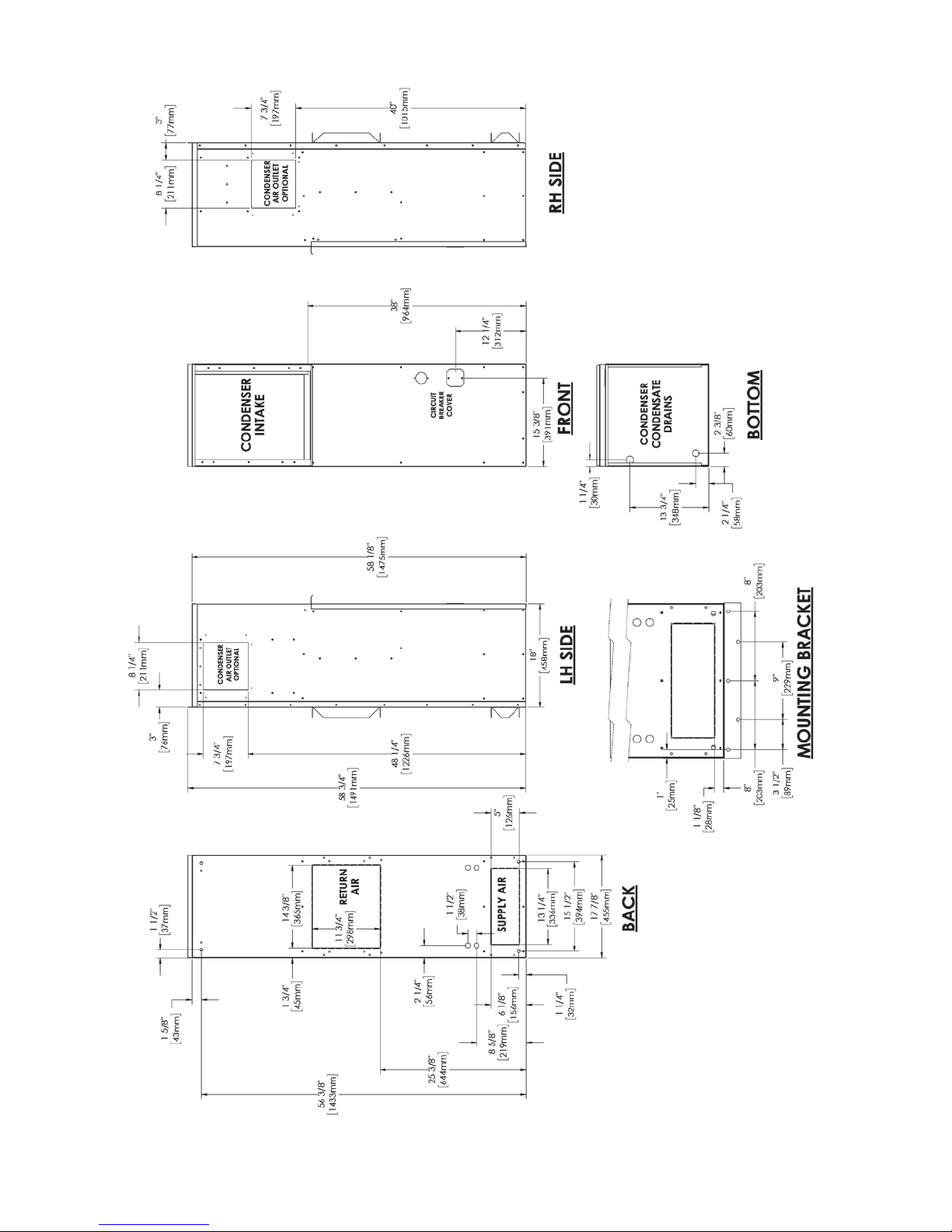
Figure 1a. Dimensional Data - ECUA12
Weight
ECUA12 160 lbs/73 kg
8
ICE SlimPac ECUA12-18 I&O Manual 03/2019 Rev.2
Figure 1b. Dimensional Data - ECUA18

9ICE SlimPac ECUA12-18 I&O Manual 03/2019 Rev.2
1.5 General Operation
Refrigerant Cycle (Cooling Mode)
The SlimPac™ uses R-410A refrigerant in a conventional vapor-compression refrigeration cycle to
transfer heat from air in an enclosed space to the outside. A supply blower assembly pulls indoor air
across the evaporator. Liquid refrigerant passing through the evaporator is boiled into gas by heat
removed from the air. The warmed refrigerant gas enters the compressor where its temperature and
pressure are increased. The hot refrigerant gas condenses to liquid as heat is transferred to outdoor air
drawn across the condenser by the condenser fan. Liquid refrigerant is expanded into the evaporator
through the metering device to repeat the cycle.
Cooling Mode: The compressor and condenser fan are energized with a contactor controlled by a 24
VAC pilot signal (see Figures 2a and 2b). The outside fan or blower motor is controlled by the head
pressure control (see head pressure control, section 1.7). The supply air blowers are energized by the
blower relay.
Heating Mode: A wall-mounted thermostat controls the heating cycle of models which incorporate
resistance heating elements. On a call for heat, the thermostat closes the heat relay to energize the indoor
blower and the resistance elements.
10
ICE SlimPac ECUA12-18 I&O Manual 03/2019 Rev.2
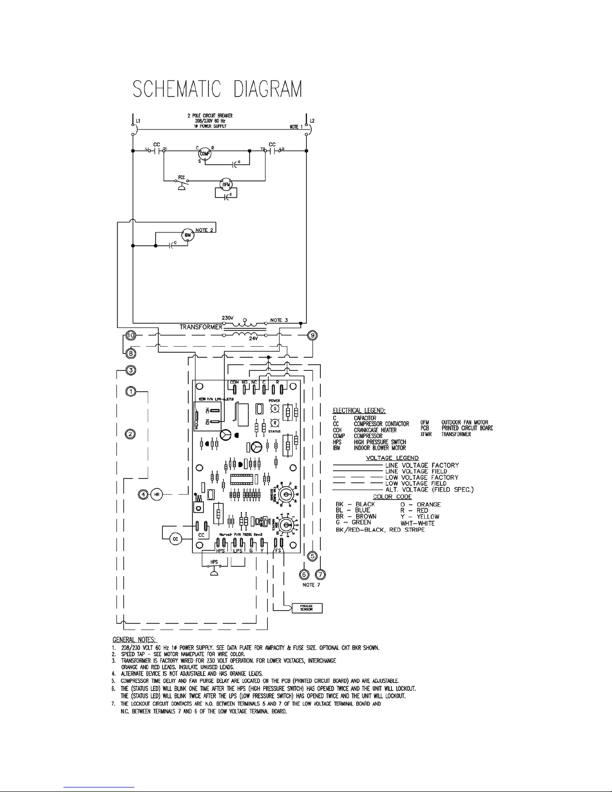
1.6 Electrical Diagrams
Figure 2a. Typical Electrical Schematic - ECUA12
Dieses Handbuch passt für folgende Modelle
1
Inhaltsverzeichnis
Andere Industrial Climate Engineering Klimaanlage Handbücher


