Jolly Mec Control Display Bedienungsanleitung

SM096 EN REV03 2016_05
CONTROL
DISPLAY
USER MANUAL
To be kept by the purchaser
Control display for water heating products

Dear Customer,
thank you for having chosen to heat and save with a Jolly Mec product. Please carefully read and keep this sheet
before using the equipment.
The manual provides information and suggestions necessary for correct product use. Knowing and observing these
instructions will allow you to fully and safely enjoy the potential your equipment can offer you.

SM096 EN REV03 2016_05 3
ENGLISH
TABLE OF CONTENTS
CHAP.01 PREMISES...................................................................................................................................4
01.1 WARNINGS .................................................................................................................................................. 4
01.2 SYMBOLOGY............................................................................................................................................... 4
CHAP.02 USER INTERFACE...................................................................................................................... 5
02.1 CONTROL DISPLAY DESCRIPTION........................................................................................................... 5
02.2 KEY FUNCTIONS......................................................................................................................................... 5
02.3 ICON MEANINGS......................................................................................................................................... 6
CAP.03 OPERATING MODE ....................................................................................................................6
03.1 APPLIANCE OPERATIONS ......................................................................................................................... 6
03.2 MAIN STATUS MESSAGE MEANINGS ....................................................................................................... 7
03.3 MAIN SETTINGS.......................................................................................................................................... 8
CHAP.04 USER MENU................................................................................................................................9
04.1 FUNCTIONS................................................................................................................................................. 9
04.2 STRUCTURE.............................................................................................................................................. 10
CHAP.05 FAULT DIAGNOSIS AND TROUBLESHOOTING ....................................................................23
05.1 ALARM MESSAGES .................................................................................................................................. 23

4
CHAP.01 PREMISES
01.1 WARNINGS
• Werecommendyoucarefullyreadandfollowtheinstructionsinthismanualforcorrectuse.
• Itshouldbekeptwithcareandattentivelyconsultedsinceallthewarningsprovideimportantsafetyinstructions.
• Incorrectusecouldcausedamageandinjurytopeople,animalsorproperty,forwhichthemanufacturercannotnotbeheldliable.
• Theappliancemustbeusedonlyforitsintendedpurpose.Anyotheruseisdeemedimproperandthereforedangerous.
• Themanufacturerdeclinesanycontractualornon-contractualliabilityfordamagescausedbyerrorsininstallationoruseofthe
applianceorfailuretofollowtheinstructionscontainedinthismanual.
• AllrightsonthereproductionofthistechnicalmanualareownedbyJollyMecCaminettiS.p.A.
• Thedescriptionsandillustrationsprovidedinthefollowingpublicationarenotbinding.
• JollyMecCaminettiS.p.Areservestherighttomakeanymodicationsthatmaybedeemedappropriate.
• ThismanualcannotbegiventothirdpartiesforperusalwithoutthewrittenpermissionofJollyMecCaminettiS.p.A.
• Donotmakeanyunauthorisedmodicationtotheappliance.Anyunauthorisedmodicationwillautomaticallyinvalidatethewarranty
andreleasethemanufacturefromallliability.
• Useonlyoriginalsparepartsrecommendedbythemanufacturer.Originalsparepartsareavailablethroughretailers,specialised
TecnicalServiceCenters,ordirectlyattheheadofceofJollyMecCaminettiS.p.A.
01.2 SYMBOLOGY
In this manual, points of considerable importance are marked with the following symbology:
INSTRUCTION: Instructions regarding the correct use of the appliance.
WARNING: This point is particularly important.

ENGLISH
CHAP.02 USER INTERFACE
02.1 CONTROL DISPLAY DESCRIPTION
The control display lets you communicate with the control unit. The keys are used to transmit commands to the control unit while the
display informs the user on stove operating status. Programming mode displays the various settings that can be edited using the keys.
02.2 KEY FUNCTIONS
Key Description Mode Action
1Temperature selection
QUICK ACCESS Rapid access to adjust Set ambient temperature
Increase
EDIT VALUE Increases the selected setting value
Chronothermostat
ACTIVATE CRONO Pressed together with button 2 activates the Timer function.
2Temperature selection
QUICK ACCESS Rapid access to adjust Set Water temperature in the appliance
Decrease
EDIT VALUE Decreases the selected setting value
Chronothermostat
ACTIVATE CRONO Pressed together with button 2 activates the Timer function
3On/Off - Esc - REsEt
OFF Turns on
WORK Turns off
ALARM Resets the alarm
MENU Returns to the previous level
4Access Menu/Conrm
OFF Opens the menu
WORK Opens the menu
MENU Conrms changed settings and moves to the next Menu page
5Output selection
QUICK ACCESS Rapid access to set the power
Increase
EDIT VALUE Increases output value
Decrease page
MENU Change page within the Menu
6Temperature selection
QUICK ACCESS Rapid inlet to regulate Set Temperature Puffer and Boiler
Decrease
EDIT VALUE Decreases output value
Increase page
MENU Changes page within the menu
1
23
4
6
5
5
Display
IR receiver
Component reference icons

6
02.3 ICON MEANINGS
A segment may or may not be found next to each icon on the display to indicate whether or not the relevant component and/or function
is enabled. The functions or components associated with the various icons are:
The image below depicts an example of a display screen which indicates that the chronothermostat function is running and the auger
gear motor and electrical resistance are running.
The rst row on the display shows the current time, the second row shows, from the left, room temperature and water temperature, whilst
the third and fourth rows show, respectively, the device status and operating output.
Room probe request Auger gear motor
Chronothermostat Fume fan
Electrical resistance Water circulator
Auxiliary circulator Alarm
CAP.03 OPERATING MODE
03.1 APPLIANCE OPERATIONS
When the appliance is OFF, press and hold down Key 3 on the display for several seconds to turn it on. Next, the start-up message will
appear on the display indicating that the switch-on procedure is made up of various phases dened in technical parameter settings and
to be set by a specialised Technical Service Center. After the normal switch-on time, the device normally reaches the RUNNING condition
at the set output unless fume temperature reaches the minimum admitted value and the relevant alarm message is displayed. In normal
conditions the device maintains work status, running the BASKET CLEANING mode at set intervals until the set room temperature is
reached (or other temperature according to the probe or set system conguration). Afterwards, it switches to ECO MODULAT- mode
running at reduced regime. If STAND-BY mode is on, the device turns off after a period of time in economy mode or after this condition
led to a certain increase in the reference temperature. The length of this period and the temperature increase can be set in MENU 5 –
STAND BY. In STAND-BY mode, the stove automatically turns back on when the reference temperature drops under the set value. To
manually turn off the stove, simply press and hold down Key 3 for several seconds. Next, FINAL CLEANING is run.

ENGLISH
03.2 MAIN STATUS MESSAGE MEANINGS
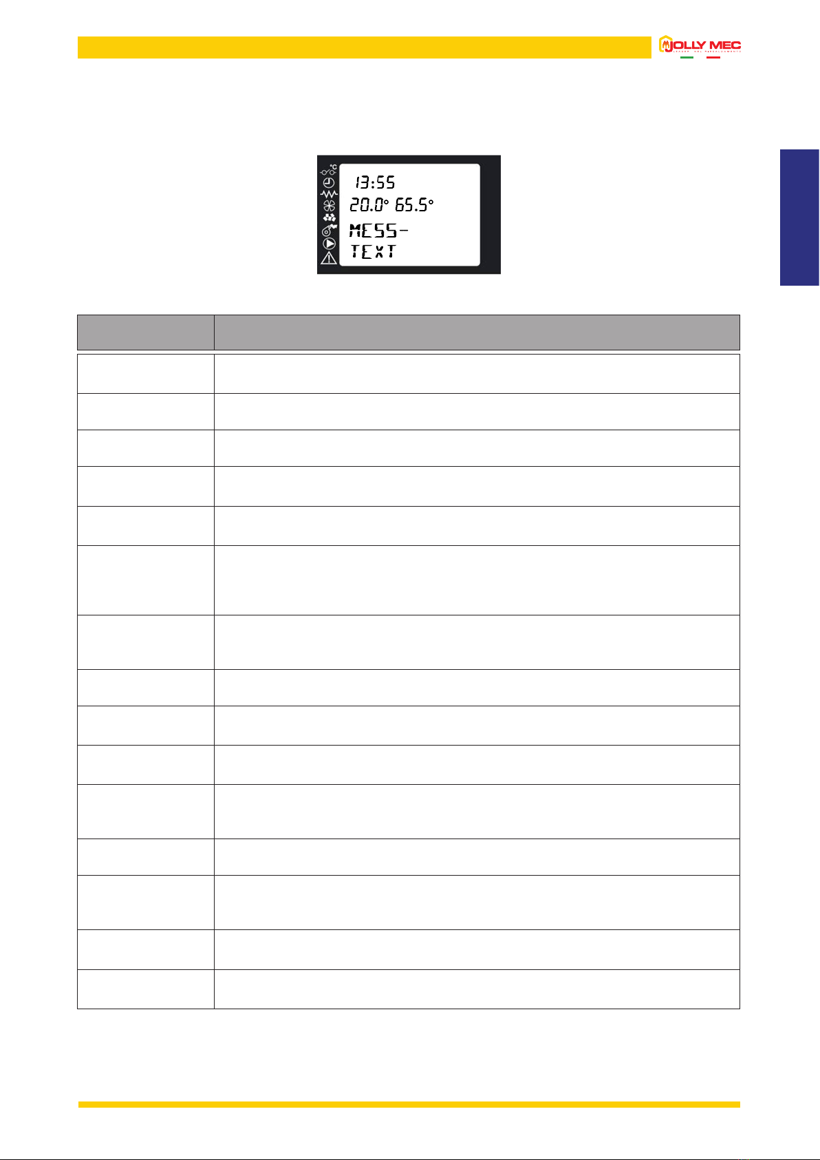
During normal operations, the screen displays the time, room temperature, water temperature and a message that indicates device status
when the message is displayed. An illustration of the main display screen appears below.
The main messages that can appear on the display and their meanings are summarised in the following table:
MESS-
TEXT Description
OFF
Message displayed when the appliance is off. It can be switched on in manual mode, using a
GPRS system or chronothermostat settings.
INITIAL
ventil-
Message displayed during the initial ventilation phase during the rst start-up phase.
PRELOAD
PELLET
Message displayed during the initial pellet preload phase.
WAIT
FLAME
Message is displayed during the stand-by time before the pellets are ignited. The fumes
temperature must reach a set value for the device to be considered ON.
fLAME
ON
Message displayed when the device is on. This message remains on the screen for a short
period of time while the ame stabilises and pellet ignition in the brazier is completed.
RUNNING
p0
Message displayed during device operations in work mode, meaning until the temperature read by
the room probe or water probe reaches the set value.
The number indicated next to the letter P indicates the output level at which the device is running.
If the number ashes, the device is increasing or decreasing output.
BASKET
CLEANING
Message displayed during the clean brazier automatic cycle that is run at regular intervals
while the stove is running. A forced ventilation cycle of the fumes extractor removes any excess
unburned materials from the brazier.
final
CLEANING
Message displayed during the shutdown phase.
eco
modulaT-
Message displayed when the room and/or water temperature value is reached. The appliance
automatically switches to economy mode.
OK
STAND-BY
The previous screen is alternated when, after a period of running in ECONOMY mode, the
device enters STAND-BY and shutdown conditions are met.
OFF
WAITING
Message displayed when, during the start phase, the switch off button is pressed. Device
shutdown during the switch-on phase is not permitted. Therefore, the command is saved and
will be run at the end of the stabilisation phase.
WAITING
COOLING
Message displayed during the shutdown phase for STAND-BY mode
WAIT
RESTART
Message displayed when, during the shutdown phase, the switch on button is pressed. Device
start during the shutdown phase is not permitted. Therefore, the command is saved and run
when the fume temperature drops under 80°C.
STAND-BY The device is OFF, waiting to be automatically restarted by a probe signal that requests heat.
The device is not completely switched off in STAND-BY status, but is OFF waiting to restart.
ORDINARY
SERVICE
The device has reached the periodic servicing warning signal, to be reset with the heating stove
OFF by pressing Key 3 on the home page.
7

8
Output settings
03.3 MAIN SETTINGS
Use the specic keys on the control display to directly access from the main page the room, stove and, according to the adopted system
conguration, the puffer and/or boiler output and temperature settings pages.
Temperature settings
To change the operating output, press Key 5on the main page to immediately open the
screen where you can use the Keys 5 or 6 to select from the ve settable output settings.
After selecting the required output level, press Key 3to return to the main page.
To change the required temperatures, press Key 1,2 or 6 on the main page to immediately open the relevant section. The set values
can be changed using keys 1 and 2 in each screen. If diagram 7 is set, press key 6 once to access the set Puffer settings, press key 6
twice to access the set Boiler settings.
After selecting the required output level, press Key 3to return to the main page.
Key 1
For all Conguration
Key 2
For all Conguration
Key 6
With Conguration 5 or 7 set.
The second row represents the temperature read by
the probe.
Key 6
With Conguration 6 or 7 set.
The second row represents the temperature read by
the probe.

ENGLISH
CHAP.04 USER MENU
04.1 FUNCTIONS
The display is divided into menus and sub-menus that can be scrolled using the control display keys. In short, main menus and their
functions are:
MENU Description
1 - SET CLOCK
Lets you set the current date and time, required for correct chronothermostat operations
2 - SET CHRONO
Lets you turn the chronothermostat and its programs on or off. The delay programme is enabled on
crono page, that independently from the crono, can be used to delay start-ups and switch-offs.
3 - SET LANGUAGE
Lets you set the menu language
4 - SET PROBE
Lets you set the type of room probe to be used.
• Set THERMOSTAT probe type to use a thermostat to control the appliance. If a retail thermostat
is used, the device must be used with clean contacts to the appliance. The Jolly Mec thermostat
module is also considered a thermostat. Therefore, if an original Jolly Mec device is used, set
THERMOSTAT as probe type.
• Set PROBE type to use the probe installed on the stove or a remote same type of probe in another
room. In the latter case, the probe installed on the stove must be disconnected from the electronic
card (to be done by a specialised Technical Service Center).
5 - SET STAND-BY
STAND-BY mode lets you turn off the appliance when room or water temperature requests, according
to the set conguration, are met. In STAND-BY (display message) the appliance is awaiting room or
accumulation tank thermostat requests to restart a switch-on cycle. The delay time delays shutdown
from the moment when the requests are met. If PROBE type was set in MENU 4, the appliance will
only shutdown after running in ECONOMY mode for a period of time equal to DELAY OFF time after
requests are met while if THERMOSTAT type is set, the appliance will run in ECONOMY mode for twice
as long as the set DELAY OFF time.
6 - SET DISPLAY
Allows you to change the device acoustic signals settings and delay the switch-off of the back-lighting.
7 - PELLET LOAD
Lets you start manual pellet load. It can be used after the completely empty tank was lled with fuel,
to ll the burner.
8 - STATE STOVE
Allows you to check the actual operating status scrolling through the various pages using Keys 5 or 6.
9 - TECHNIC SETTINGS
This menu contains the appliance settingspages that only the specialised Technical Service Center can
access using a specic password.
A - REGULATE SETTING
Lets you change pellet loading and fume exhaust settings
B - COUNTER MEMORY
Lets you read some data stored in the control unit memory
C - SEASON
Lets you set either winter or summer operating mode
9

10
04.2 STRUCTURE
To open the various menus, press Key 4when the main page is displayed on the remote control. To scroll the various menu pages, use
Keys 5and 6.
M1-001 DAY
To select the current day of the week, use Keys 1and
2and press Key 4to set the displayed value and move
to the next page.
M1-002 HOUR CLOCK
To set the hour, use Keys 1and 2and press Key 4to set
the displayed value and move to the next page.
M1-003 MINUTES CLOCK
To set the minutes, use Keys 1and 2and press Key 4
to set the displayed value and move to the next page.
M1-004 DAY CLOCK
To select the current day, use Keys 1and 2and press
Key 4 to set the displayed value and move to the next
page.
M1-005 MONTH CLOCK
To select the current month, use Keys 1and 2 and press
Key 4 to set the displayed value and move to the next
page.
M1-006 YEAR CLOCK
To select the current year, use Keys 1and 2 and press
Key 4 to set the displayed value and move to the next
page.
When nished, the message DONE will be displayed
to conrm correct data entry. Next, the level page
automatically returns to the Menu Page.
MENU 1 - SET CLOCK
4
3
3
3
3
3
3
4 5
4 5
4 5
4 5
4 5
4
Inhaltsverzeichnis
Andere Jolly Mec Steuereinheit Handbücher
Beliebte Steuereinheit Handbücher anderer Marken

Festo
Festo Compact Performance CP-FB6-E Stücklistenhandbuch

Elo TouchSystems
Elo TouchSystems DMS-SA19P-EXTME Bedienungsanleitung

JS Automation
JS Automation MPC3034A Bedienungsanleitung

JAUDT
JAUDT SW GII 6406 Series Kurzanleitung

Spektrum
Spektrum Air Module System Bedienungsanleitung

BOC Edwards
BOC Edwards Q Series Bedienungsanleitung


