Jomox ModBase 09 MkII Bedienungsanleitung

Version OS 2.07
ModBase 09 MkII
Euro-Rack Analog Kick Drum Synthesizer Module
Operating Manual
ModBase 09 MkII Operating Manual 1

Version OS 2.07
Contents
Introduction.............................................................................................4
1. Installation...........................................................................................5
1.1. Installation in the eurorack.............................................................
1.1. Midi In...........................................................................................8
1.2. Midi Out........................................................................................8
1.3. Akasha Module Bus........................................................................8
2. Front connections.................................................................................9
2.1. CV1-CV4........................................................................................9
2.2. LIN.FM..........................................................................................9
2.3. ACC.............................................................................................10
2.4. GATE...........................................................................................10
2.5. OUT............................................................................................10
3. General functions................................................................................11
3.1. Preset selection < P00-P99 >......................................................11
3.2. Menu control................................................................................11
3.3. Midi control..................................................................................12
3.3.1. Note trigger...........................................................................12
3.3.2. Parameter control via Midi controllers.....................................13
3.4. Triggering via CV/GATE................................................................13
3.5. Triggering via ACC input
..........................................................................................................13
4. Sound parameters (potentiometers).....................................................14
4.1. Tune < 000-252 > ...................................................................15
4.2. Pitch < 000-252>......................................................................15
4.3. Decay < 000-252 > ..................................................................15
4.4. Harmonics < 000-252>.............................................................15
4.5. Pulse < 000-252 >....................................................................15
4. . Noise < 000-252 >....................................................................1
4.7. Attack < 000-252 > .................................................................1
4.8. EQ < 000-252 > .....................................................................1
5. Sound parameters (menu orange/red)................................................17
5.1. LFO.............................................................................................17
5.1.1. LFO 1 Wave < SuP / Sdo / Sin / Si- / tri / tr- / rCt / rC- >............17
5.1.2. LFO 1 Speed < 000-252 >........................................................18
2 ModBase 09 MkII Operating Manual

Version OS 2.07
5.1.3. LFO 1 Int(ensity) < 000-252 >..................................................18
5.1.4. LFO 1 Destination <LM1/no1>..................................................19
5.1.5. LFO 2.......................................................................................19
5.2. Gate T(ime) (page orange) < 000-255> .......................................19
5.2.1. Preset Init (page red) <in?>......................................................19
5.3. Compr(ression) (page red) < 000-255 > ......................................20
5.4. Met Nze 1 (page orange) < off/noi-499 > ...................................20
5.4.1. MetNze 2 (page red) < off-499 > ...........................................21
5.4.2. MetNze 2 bit mask (page red blinks) <M01-M1 >.......................21
5.5. CV 1-4.........................................................................................21
5.5.1. CV 1-4 Destination (page orange)...............................................22
5. . CV 1-4 Amount (page red) <-128 - 127>.......................................23
. Master parameters (menu green)........................................................24
.1. Midi Ch(annel) < 001 - 01 >.....................................................24
.2. Split Mode < SM1 / SM2 >.........................................................24
.3. Acc Sens(ivity) < t01- t99 >.....................................................24
.3.1. Acc Dynamics < d01- d 3 >...................................................25
.4. Gate Mode <PoS/neg/Str/ACC>..................................................25
.5. Volume < 000-255 > .................................................................2
. . Bus Env < 000-255 >.................................................................2
.7. Fine Tune CV (hidden) < 000-255 >............................................2
.8. Store...........................................................................................2
7. ModBase 09 MkII Midi implementation.................................................27
7.1. SysEx Dump.............................................................................27
7.1.1. Single preset dump................................................................27
7.1.2. All presets dump....................................................................27
7.1.3. Receive SysEx dump..............................................................27
7.2. Sound Parameter CC....................................................................28
7.3. Note Commands...........................................................................29
7.4. System exclusive data..................................................................29
ModBase 09 MkII Operating Manual 3

Version OS 2.07
Introduction
Thanks for using the JoMoX ModBase 09 MkII! The ModBase 09 MkII is a
great sounding, dedicated kick drum module with a real analog sound
production made for installation in 19 inch euroracks as offered by
companies like Doepfer GmbH for instance.
Actually it is a single voice storeable analog synthesizer which is optimized to
produce professional club compatible kick drum sounds. The ModBase 09
MkII module is fully controllable by CV (control voltage) / Gate as well as via
Midi. All sound parameters can be remotely controlled by either the 4 CV
inputs or via Midi CC.
All jacks are being made as 3.5mm mini jacks which is the standard in
eurorack world. You can find suitable cables in the accessories of many
eurorack modular system producing companies.
The usage is fairly simple and self-explaining at most points. Nevertheless,
we recommend to study this manual intensively in order to explore the
manyfold musical possibilities of the ModBase 09 MkII as quickly as possible.
Before we start just some important safety instructions:
Please use the ModBase 09 MkII only in dry rooms. Please never let
fluids or humidity penetrate to the device!
The module is only made for use in so-called eurorack modular systems.
A 1 pin ribbon cable for the connection to the Doepfer system bus with
+/-12V is added. The supply voltages may not exceed +/- 15Volts.
Although there are protection diodes inside against wrong polarity we
have to warn you about wrong installation as severe damadge may
happen to the device! On a damadge caused by wrong installation or
modification of supply pins the warranty is void.
For cleansing of the ModBase 09 MkII, please use a slightly damp cloth,
never solvents or agents!
The ModBase 09 MkII is a complex electronic device and should
therefore be treated carefully!
If any damadges or malfunctions occur, please immediatly turn off the rack,
take the module out of the rack and contact your local music dealer or send
an email to [email protected].
4 ModBase 09 MkII Operating Manual
Version OS 2.07
1. Installation
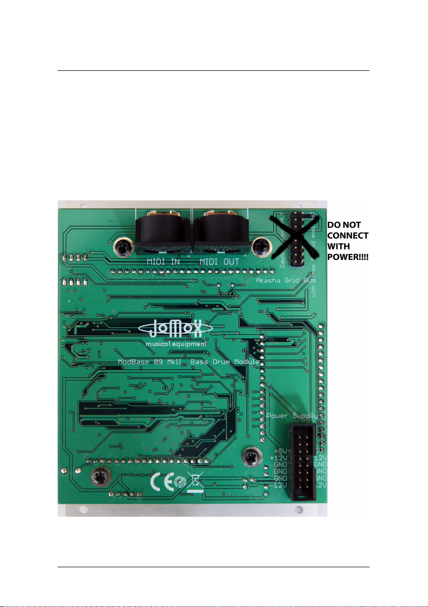
Please turn off the euro rack prior to the wiring! On the backside of the
ModBase 09 MkII module you can find these connections:
ModBase 09 MkII Operating Manual 5

Version OS 2.07
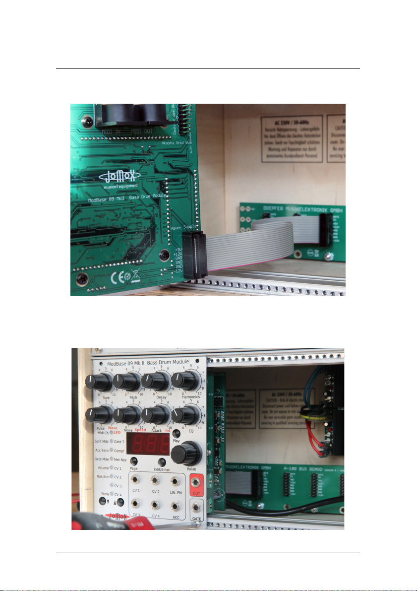
1.1. Installation in the eurorack
Please connect the supplied ribbon cable to the eurorack system bus rails as
shown on the picture. The module needs +/-12 Volts at a supply current of
maximum 140mA on +12V and about 80mA on -12 Volts. The optional 5
Volts and the CV/Gate on the A-100 Doepfer bus are both not wired inside
the Jomox modules and not needed. Other 10 pin systems may be used as
well if only the lower part of the 1 pin connector is connected. Please pay
attention for the position of the voltages and the ground pins! There are
protection diodes inside the modules but please take extra care to protect
the rack and the module!
A-100 Doepfer bus. (The Doepfer GmbH
enterprise and all of their shown
products are registered trademarks. With
friendly approval of Doepfer
Musikelektronik GmbH)
Jomox ModBase 09 MkII euro rack
supply connector.
Please connect the power supply of
the eurorack system bus
here – and
only here!
Connect the other end of the ribbon
cable to the module as shown on the
picture. The cables are fairly short
which is good in electrical means to
the relatively high power consumption
of the module.
ModBase 09 MkII Operating Manual
Version OS 2.07
Don't flip the cable but connect it as shown on the picture.
Then please mount the module on the rack rails with the supplied metric M3
screws. In case you want to connect a midi cable, please do this beforehand
of mounting.
ModBase 09 MkII Operating Manual 7

Version OS 2.07
1.1. Midi In
Here you can hook up another midi device to control the ModBase 09 MkII
by either a software sequencer, a controller box or any other hardware
device like e.g. a JoMoX XBase09, XBASE999/888. Please use a cable that is
as short as possible.
1.2. Midi Out
Sends out Midi data from the ModBase 09 MkII to a Midi capable device,
e.g. a soft- or hardware sequencer. The Midi Out jack also serves as a Midi
Thru and forwards Midi data to an eventual neighbour module by Jomox.
Please use a standard midi cable that is as short as possible.
1.3. Akasha Module Bus
This is an internal Jomox bus which can be connected to future experimental
sound modules. The bus carries power supply rails, an analog send bus and
an analog input to the kick drum VCA envelope and a fast I²C link. By use of
the digital link, the modules can be hooked up with each other and form a
whole storeable main frame system.
Similar to Midi, all functions and parameters of each module can be remotely
controlled within the rack by use of the digital link, only that it is about 10
times faster than Midi.
DO NOT CONNECT THE POWER SUPPLY RIBBON CABLE HERE!!!!
8 ModBase 09 MkII Operating Manual

Version OS 2.07
2. Front connections
2.1. CV1-CV4
The inputs CV1-CV4 are programmable CV control inputs. In a modular
system, most functions and parameters like eg. VCO pitch or filter cutoff can
be controlled by a CV (control voltage). In the ModBase 09 MkII, practically
all internal sound parameters can be controlled (ie. modulated) by an
assignable CV. The modulation amount can be controlled by software, either
positively as negatively. More information you can find in chapter 5.5 CV
control.
These CV inputs can process 0-5Volts. Higher or negative voltages are
blocked inside and will not cause damadge, but they won't get processed
anyway.
2.2. IN.FM
Linear FM CV input. This connection serves to modulate the bass drum VCO
and works on the pitch (FM = frequency modulation). The FM CV input is
just analogue and can't be controlled by software. Therefore it works over
ModBase 09 MkII Operating Manual 9

Version OS 2.07
the entire audio range and the frequency resolution is not limited by the
sampling rate of the CPU. Since the input has no amount knob, one should
put an attenuator (it may be passive, means a potentiometer) into the signal
chain because otherwise modulation occurs at full intensity of the
modulating signal (eg. LFO). This input processes also negative voltages.
2.3. ACC
The ACC input serves for the accent. The applied CV can control the kick
drum dynamics as well as trigger directly dynamically if the master
sequencer allows for this feature. In normal mode (Gate Mode = Pos, Neg
or S-Trig) the accent CV is taken in the moment of trigger and controls the
volume (dynamics) of the kick drum.
If, however, the Gate Mode is set to <ACC> (see .4 Gate Mode), the kick
drum can be triggered just by the accent CV. This requires that the
sequencer is capable of producing pulses with a defined accent CV that have
to go back to zero each time. The settings around accent dynamics and the
accent threshold can be found in chapter .3. Acc Sens(ivity).
2.4. GATE
The gate input of a typical modular environment is the input which is used
to trigger the tone of the ModBase 09 MkII. The typical gate high signals
used in modular world have normally 5-15 volts, which the gate input of the
ModBase 09 MkII can process without any problems – the threshold is at
about 1 volts. The gate polarity can be inverted by software too.
Furthermore, some modular systems use a special kind of triggering called
S-trig (switch trigger) which the ModBase 09 MkII can do as a software
feature too. In this case the triggering is excited if the tip (hot wire) and ring
(=ground) of the gate cable plug are shorted – be it electronical by a
transistor or mechanical by a simple switch.
2.5. OUT
Audio ouput signal of the ModBase 09 MkII. The ouput is unbalanced and
has a maximum level of about +20 dBu, so it can be very loud and may
overdrive high gain inputs. Therefore connect the audio output with an
appropriate attenuator/mixer or amplifier.
10 ModBase 09 MkII Operating Manual
Inhaltsverzeichnis
Andere Jomox Synthesizer Handbücher


