Jordan Valve Mark 39 Montage- und Bedienungsanleitung

6. The flow arrow on the valve body must be pointed in the
direction of flow. Ideally, the valve should be installed in the
highest horizontal line of piping to provide drainage for
inlet and outlet piping, to prevent water hammer, and to
obtain faster response.
7. If possible, install a relief valve downstream from the valve.
Set at 15 psi above the control point of the valve.
8. In hot vapor lines, upstream and downstream piping near
the valve should be insulated to minimize condensation.
9. In gas service, if the control pressure (downstream) is 25%
of the inlet pressure or less, expand the outlet piping at
leastonepipesize. Astandard taperedexpander connected
to the outlet of the valve is recommended.
10. Where surges are severe, a piping accumulator is recom-
mended.
11. On steam control applications, install a steam trap with suf-
ficient capacity to drain the coil or condenser. Be sure to
have a good fall to the trap, and no backpressure. Best
control is maintained if the coil or condenser is kept dry.
Trouble Shooting
Trouble Possible Cause & Cure
Erratic Control
Will Not Operate
Wiring
Please read these instructions carefully!
Your Jordan Valve product will provide you with long, trouble-
free service if it is correctly installed and maintained. Spend-
ing a few minutes now reading these instructions can save
hours of trouble and downtime later. When making repairs,
use only genuine Jordan Valve parts, available for immediate
shipment from the factory.
Ideal Installation Schematic
Preferred Installation
1. To protect the valve from grit, scale, thread chips and other
foreign matter, ALL pipelinesand pipingcomponents should
be blown out and thoroughly cleaned before the installa-
tion process begins.
2. Shutoff valves, pressure gauges and by-pass piping should
be installed as indicated in the Ideal Installation Schematic
to provide easier adjustment, operation, and testing.
3. A line strainer should be installed on the inlet side of the
valve to protect it from grit, scale and other foreign matter.A
.033 perforated screen is usually suitable for this purpose.
Line strainers are available from Jordan Valve.
4. For best control, 3’-0” straight sections of pipe should be
installed on either side of the valve.
5. In preparing threaded pipe connections, care should be
exercised to prevent pipe-sealing compound from getting
into the pipelines. Pipe-sealing compound should be used
sparingly, leaving the two end threads clean. Jordan uses,
and recommends, thread sealer Teflon ribbon
Warning: JordanValve Control Valves must only be used, installed, and repaired in accordance with these Installation &
Maintenance Instructions. Observe all applicable public and company codes and regulations. In the event of leakage or
othermalfunction, call a qualified service person;continued operation may cause system failureor a general hazard.
Before servicing any valve, disconnect, shut off, or bypass all pressurized fluid. Before disassembling a valve, be sure to
releaseallspringtension.
PROTECTVALVESWITH LINE STRAINERS
3170 Wasson Road • Cincinnati, OH 45209 USA
Phone 513-533-5600 • Fax 513-871-0105
E-Mail: info@richardsind.com • www.jordanvalve.com
I&M 39/39MX
Installation & Maintenance Instructions for
Mark 39 Electric Motor Actuated 3Way Valve
Oversizing causes cycling and hunting
and reduces the rangeability of the valve.
Make certain that your sizing is correct.
Steam traps downstream may need
attention.
Excessive foreign matter on seats. Clean
them.
Valve stroke out of adjustment. Check and
readjust if necessary.
Valve disc may not be moving freely.
Electrical power off or loose connection.
Defective control device.
Defective motor.
See the motor manufacturer’s literature, supplied with the
valve, for wiring connections and instructions.
Caution: Disconnect electrical power supply before wiring
motor into circuit to avoid electrical shock or possible
damage to equipment. Always disconnect power supply
before attempting any wiring changes.

two nuts. Lift the cap straight up.
3. Before removing, check the disc for a stamped arrow. This
arrow points to the “<”on the body.
. (NOTE: certain discs that can be rotated 180° without
affecting the stroke might not have an arrow.)
4. Remove the disc guide (18) by lifting straight up. Also lift
straight up on the disc. Place the disc on the bench,
lapped surface facing up. Protect the lapped surfaces on
both sides of the disc guide.
5. Invert the body and lightly tap on the exterior to remove the
plate. Let the plate drop out into your hand, and place it on
the bench with the lapped surface facing up.
6. Clean all of the parts, body and cap with solvent. Place a
piece of 4/0 polishing cloth or jewelers cloth on a smooth,
flat surface, and polish the lapped seating surfaces of the
disc, plate, and disc guide using a figure “8” motion. If the
parts are scarred, do not attempt to relap them, but return
them to the factory for repair or replacement. Often parts
canbe repairedat a minimalcost ifthe partsare notscarred
too deeply.
7. The vertical sections of the disc guide serve as guides for
the disc while stroking. A 0.005 feeler gauge should be
used to check for clearance between this surface and the
side of the disc. If the clearance is less, clean the guide
surfaces in the disc guide with a fine file.
Start-Up
Valve Maintenance
Caution: Make certain that there is no pressure in the valve
before loosening any fittings or joints. The following steps
are recommended:
1. Close the inlet shutoff valve.
2. Allow pressure to bleed off through downstream piping.
Do not attempt to reverse the valve by bleeding pressure
from the upstream side of the valve.
3. When the pressure gauges indicate that all pressure has
beenremovedfrom thesystem,close theoutletshutoffvalve,
and the valve may be serviced.
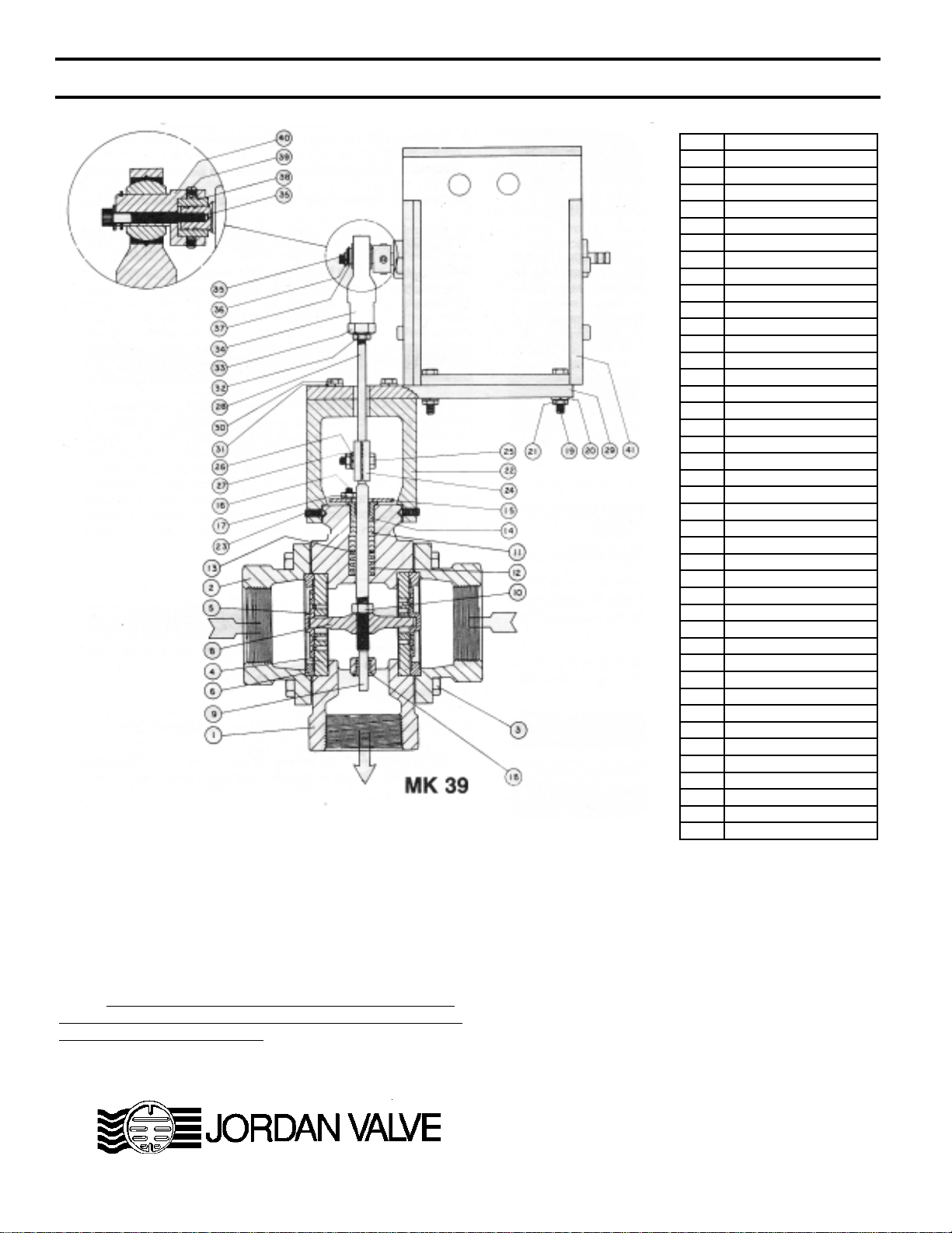
Note: refer to the drawing at the end of this document for
description and proper orientation of parts.
Valve Seats
A. DISASSEMBLY Stem, Disc & Pin Replacement
B. REASSEMBLY
1. Fully open the outlet shutoff valve.
2. Slowly open the inlet shutoff valve.
3. Do not fully open the inlet shutoff valve until you are sure
that the controller and control valve have control of the
system.
1. Follow the Maintenance Procedure and remove the valve
from line.
2. Note the scribes “<” on the side of the valve body and cap.
Secure the body flats in a vise. Remove the cap bolts and
1. Place the plate in the body, lapped surface facing the cap.
The index pin hole should be on the same side of the body
asthe“<”onthe body.Align thedisc pinso thatitis centered
in the body bore and that it protrudes through the center
slot in the valve plate (this should be the longer of the two
extensions if the disc pin is cast).
2. Place the disc on the valve plate, engaging the disc pin.
The arrow on the disc should point to the index pinhole.
Insert the index pin in the hole.
3. Place the disc guide onto the valve plate, engaging the
index pin. Rotate the assembly slightly until the slot
openings in the disc are parallel to the openings in the
plate and perpendicular to the stem. Stroking the valve will
aide in this alignment.
4. Align the“>”on the cap with the “<”on the body, and place
the cap over the two studs in the body.
5. Install the nuts and cap bolts.Tighten uniformly. See back
page for torque requirements and tightening procedures.
Repeat disassembly and reassembly per “A” and “B”
above for the second set of seats
1. Remove the disc and plate, following the procedure
outlined under VALVE SEATS.
2. Loosen the stem connector nut and bolt and remove
connector.
3. Back out the four allen head yoke screws, which will allow
the body to be separated from the yoke.
4. Remove the packing flange nuts and the packing flange.
5. Loosen the stem locknut and rotate the disc-pin counter-
clockwise, pulling the valve stem upward while doing so.
6. When pulling the stem completely out of the body you will
remove most of the packing assembly also.The remaining
parts of the packing assembly can “fished” out with a small
screwdriver.
Cap Disc Guide
Valve Disc
Valve Plate
Studs (2)
Hex Nuts (2)
Cap Screws
Disc Pin
Index Pin
19
18
17
16
14
21
20
Body 12
Theslidinggate seatsof JordanValvesarelapped
tolight bandflatness. Maintainingsuchtolerances
is of paramount importance for your assurance
of excellent control and tight shutoff. Do Not use
metallic objects in removing the seats. Care in
handling is imperative.

VALVE STROKE ADJUSTMENT
Motor Replacement
The valve stroke is set at the factory and no field adjustments
are necessary. The position of the seats can be adjusted by
starting from the normally open position (when the orifice in the
plate and disc are perfectly aligned). For direct acting service,
adjust the motor rotation to the full CCW position (as viewed
fromthe powerend).For reverseacting service,adjust themotor
rotationto the CWposition. Ifthe seatsare notproperly fullopen,
loosen the nut that locks the actuator stem to the rod bearing
and loosen the stem connector assembly just enough to rotate
the actuator stem. Carefully thread the actuator stem in or out of
thee rod end bearing until the seats are full open and in perfect
alignment. If further adjustments are necessary, consult factory.
1. Follow procedures under the Maintenance Section to
remove the valve from line.
2. Remove socket head screw and lockwasher.
3. Important - Note the position of the cam on the motor
shaft.
4. Do Not attempt to remove the socket set screws.
5. Remove the four motor mounting bolts, lockwashers, and
nuts,
6. Slide motor back off of the mounting plate.
7. Install new motor on mounting plate.
8. Important - Make sure cam is in the same lobe position
as described in step 2.
9. Replace and tighten mounting bolts, lockwashers, and
nuts.
10. Replace and tighten socket head screw and lockwasher
on motor shaft.
11. Check valve stroke as described in STROKE
ADJUSTMENT.
Motor Maintenance
The drive motor and gear train are immersed in oil and sealed in
a die cast enclosure and thus, periodic maintenance is not
required. Field repairs must not be made. Replacement
actuators may be obtained through the nearest Jordan Valve
representative. When ordering a replacement actuator, please
provide the serial number of the valve as shown on the valve
name plate.
7. Clean the packing bore in the body with solvent and blow
dry.
8. The disc-pin may be removed through the body bore.
9. Clean the stem and disc-pin with solvent if they are to be
reused.
10. Reassemble the disc-pin, stem and locknut in the valve
body as they originally were.
11. Replace the packing spring and packing retainer in the
packing bore.
12. Reassemble the new packing on the stem with the open
part of the “V” downward (^).
There will be a flat on the top
and bottom of the stack.
Place the packing follower on top
of the packing.
13. Gently push the packing into the packing bore and place
the packing flange on the stem and over the packing studs.
14. Put on the flange nuts and tighten them partially. At this
point it is recommended that you gently move the stem up
and down three or four times to align the assembly.
15. Tighten the flange nuts until the packing follower bottoms
out on the top of the body.
16. Replace actuator in reverse order. Reassemble the valve
by inserting seats as outlined in Valve Assembly Section
for the size valve you are working with.. Then follow
instructions for STROKE ADJUSTMENT.
Torque Values
TORQUE FOR BOLTS (3) CONNECTING
VALVE CAPTOVALVE BODY (in.- lbs.)
eziSevlaV lairetaMydoBevlaV elitcuD,norItsaC eznorB,norI leetStsaC leetSsselniatS
"2&"2/1-1041051
6 bolts
(or multiples) 8 bolts
(or multiples)
BOLT PATTERN/TORQUING SEQUENCE

1-1/2”- 2”Mark 39 Electric Motor Actuated 3 Way Valve
WHEN ORDERING SPARE PART, SPECIFY:
1. Valve serial number
2. Type of valve (PRV,TCV, DCV, etc.)
3. Body size and material
4. End connection (if flanged, give rating)
5. Spring range
6. Refer to parts list above and specify part number and
name.
3170Wasson Road•Cincinnati,OH45209
Phone513-533-5600•Fax513-871-0105
PhoneToll-Free:800-543-7311(USA)
E-Mail:[email protected]
URL:www.jordanvalve.com
NOTE: Any parts ordered without a valve serial number that
are found to be incorrect are subject to up to a minimum 25%
restock charge when returned.
.oNnoitpircseD
1ydoB
2paC
3tloB
4etalP
5csiD
6ediuGcsiD
7)nwohstoN(niPxednI
8niPcsiD
9metS
01tunkcoL
11gnikcaP
21gnirpSgnikcaP
31reniateRgnikcaP
41rewolloFgnikcaP
51egnalFgnikcaP
61dutSgnikcaP
71tuNgnikcaP
81gnihsuBmetS
91wercSpaC
02rehsawkcoL
12tuN
22ekoY
32wercSteS
42rotcennoCmetS
52wercSpaC
62rehsawkcoL
72tuN
82metSrotautcA
92etalPgnitnuoM
03tloB
13rehsawkcoL
23tunkcoL
33retpadA
43gniraeBdnEdoR
53wercStekcoS
63rehsawkcoL
73gniRgniniateR
83gnihsuBhcaorB
93wercSteS
04maC
14rotoM
MK39IM-0201 L
Dieses Handbuch passt für folgende Modelle
1
Inhaltsverzeichnis
Andere Jordan Valve Steuereinheit Handbücher
Beliebte Steuereinheit Handbücher anderer Marken

Festo
Festo Compact Performance CP-FB6-E Stücklistenhandbuch

Elo TouchSystems
Elo TouchSystems DMS-SA19P-EXTME Bedienungsanleitung

JS Automation
JS Automation MPC3034A Bedienungsanleitung

JAUDT
JAUDT SW GII 6406 Series Kurzanleitung

Spektrum
Spektrum Air Module System Bedienungsanleitung

BOC Edwards
BOC Edwards Q Series Bedienungsanleitung