Juniper NFX350 Bedienungsanleitung

Quick Start Guide
NFX350 Network Services Platform Quick Start
IN THIS GUIDE
NFX350 Network Services Platform Overview | 1
NFX350 Front Panel and Rear Panel | 3
Mounting an NFX350 Device on Four Posts in a Rack or Cabinet | 3
Connect Power to the Device | 6
Factory-Default Settings | 7
Access the NFX350 Device | 7
Establish the Connection | 9
Next Steps | 10
Safety Warnings Summary | 10
Reference | 11
NFX350 Network Services Platform Overview
The Juniper Networks NFX350 Network Services Platform is a secure, automated, software-driven universal customer
premises equipment (uCPE) platform that delivers virtualized network and security services on demand. Leveraging Network
Functions Virtualization (NFV) and built on the Juniper Cloud CPE solution, NFX350 enables service providers to deploy
and chain multiple, secure, high-performance virtualized network functions (VNFs) on a single device.
The NFX350 is suited for large and extra-large deployments. The NFX350 is a high-end resilient uCPE platform that can
be used in secure SD-WAN and secure router deployments.
For more information on NFX350 Hardware, see the NFX350 Hardware Guide available at:
https://www.juniper.net/documentation/en_US/release-independent/junos/information-products/pathway-pages/nfx-series/product/

Package Contents
The NFX350 device is shipped with the following parts:
•A four-post rack-mount kit
•An AC power cord with plugs appropriate for your geographical location
•An AC power cord retainer clip
•End-user license agreement
•Documentation roadmap card
•RJ-45 cable and RJ-45 to DB-9 serial port adapter
Register the Product
Register product serial numbers on the Juniper Networks website and update the installation base data if there is any
addition or change to the installation base or if the installation base is moved. Juniper Networks will not be held accountable
for not meeting the hardware replacement service-level agreement for products that do not have registered serial numbers
or accurate installation base data.
Register your product at https://tools.juniper.net/svcreg/SRegSerialNum.jsp.
Update your installation base at https://www.juniper.net/customers/csc/management/updateinstallbase.jsp.
2
NFX350 Front Panel and Rear Panel
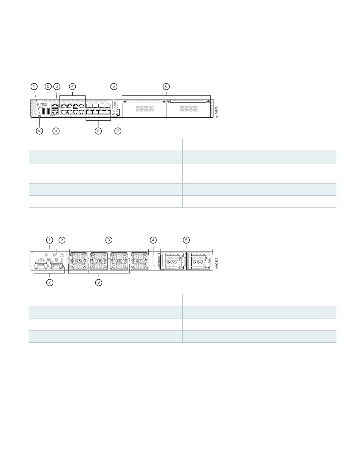
Figure 1: Front Panel Components of NFX350
g100800
65
41 32
8 710 9
6—1—Two expansion slotsReset button
7—2—SSD and slot status LEDsTwo USB 3.0 ports
8—3—Eight 1-Gigabit Ethernet/10-Gigabit Ethernet SFP+ WAN
ports
One 10/100/ 1000BASE-T RJ-45 management port
9—4—RJ-45 console portEight 10/100/ 1000BASE-T RJ-45 LAN ports
10—5—Mini-USB console portSystem status LEDs
Figure 2: Rear Panel Components of NFX350
g100802
4
35
1 2
7 6
5—1—Two power supply unitsGrounding point
6—2—Fan status LEDsElectrostatic discharge (ESD) point
7—3—Two SSD traysFour fans
4—CLEI code
Mounting an NFX350 Device on Four Posts in a Rack or
Cabinet
To mount an NFX350 device on a rack, you require the parts that are shipped with the device along with the following
additional parts and equipment. These are not shipped with the device.
3

•Electrostatic discharge (ESD) grounding strap
•Four screws to secure the chassis and mounting bracket to the rack
•Phillips (+) screwdriver, number 2
•Management host, such as a PC or laptop, with a serial port
•Two 10-32 x .25 inch screws with #10 split-lock washer
•Two #10 flat washers
•Grounding cable (minimum 14 AWG (2 mm²), minimum 90°C wire), grounding lug (Panduit LCC10-14BWL or equivalent),
a pair of 10-32x.25-in. screws, and a pair of flat washers
4

For information about installing the grounding cable, see the NFX350 Hardware Guide available at:
https://www.juniper.net/documentation/en_US/release-independent/junos/information-products/pathway-pages/nfx-series/product/
You can mount the device a four-post rack by using the mounting brackets provided with the device.
NOTE: The device weighs approximately 9.4 lb (4.3 kg). Two persons are required for mounting the device.
NOTE: Ensure that the rack is in its permanent location, allowing adequate clearance for airflow and maintenance,
and secured to the building structure.
NOTE: If you are mounting multiple units in the rack, mount the heaviest unit at the bottom and mount the
other units from bottom to top in the order of decreasing weight.
CAUTION: Wrap and fasten one end of the ESD grounding strap around your wrist and connect the
other end to a site ESD point.
To mount the device on a rack:
1. Align the mounting brackets along the front or rear of the side panels of the chassis— depending on whether you will
front-mount or rear-mount the device—and attach the mounting brackets to the chassis by using the mounting bracket
screws. Tighten the screws.
2. Have one person grasp both sides of the device, lift the device, and position it in the rack, aligning the mounting bracket
holes with the threaded holes in the rack rail. Align the bottom hole in each mounting bracket with a hole in each rack
rail, making sure that the chassis is level.
Figure 3: Attaching the Device to the Rack
g100818
3. Have the second person use the rack-mounting screws (and cage nuts and washers if your rack requires them) to attach
the mounting brackets to the rack.
5

4. Slide the rear mounting-blades into the front-mounting brackets.
5. Attach the rear mounting-blades to the rear post by using the appropriate screws for your rack. Tighten the screws.
6. Ensure that the device chassis is level by verifying that all the screws on the front of the rack are aligned with the
screws at the back of the rack.
Connect Power to the Device
CAUTION: Wrap and fasten one end of the ESD grounding strap around your wrist and connect the
other end to a site ESD point.
NOTE: Ensure that you ground AC-powered systems by attaching one end of the grounding cable to earth
ground and the other end to the chassis grounding points.
To connect the device to the power supply:
1. Set the power switch on the device to the off (O) position.
2. Insert the power cord plug into the power source outlet and power cord coupler into the chassis power inlet.
3. Set the power switch to the on (|) position.
4. Verify that the power LED is lit green and on steadily.
Power Cable Warning (Japanese)
WARNING: The attached power cable is only for this product. Do not use this cable for another
product.
6

Factory-Default Settings
The NFX350 device is shipped with the following factory-default settings:
Table 1: Security Policies
Policy ActionDestination ZoneSource Zone
permittrusttrust
permituntrusttrust
Table 2: Interfaces
IP AddressDHCP StateSecurity ZoneInterfacePort Label
192.168.2.1/24servertrustge-0/0/0 to ge-0/0/70/0 to 0/7
ISP assignedclientuntrustxe-0/0/8 to
xe-0/0/15
0/8 to 0/15
192.168.1.1/24N/AN/Afxp0MGMT
Table 3: LTE Interfaces
IP AddressSecurity ZoneInterface
N/AN/Acl-1/1/0
ISP assigneduntrustdl0 (logical)
The NFX350 device is shipped with the following services enabled by default: DHCP, HTTPS, and TFTP.
To provide secure traffic, a basic set of screens are configured on the untrust zone.
Access the NFX350 Device
1. Ensure that the NFX350 device is powered on.
2. Connect to the console port:
a. Plug one end of the Ethernet cable into the console port on your NFX350 device.
b. Connect the other end of the Ethernet cable to the RJ-45—to—DB-9 serial port adapter shipped with your device.
7

c. Connect the RJ-45—to—DB-9 serial port adapter to the serial port on the management device. Use the following
values to configure the serial port:
Baud rate—9600; Parity—N; Data bits—8; Stop bits—1; Flow control—None.
NOTE: Alternately, you can use the USB cable to connect to the mini-USB console port on the device. To
use the mini-USB console port, you must download the USB driver from the following page and install it on
the management device:
https://www.juniper.net/support/downloads/junos.html
3. Use any terminal emulation program, such as HyperTerminal, to connect to the device console. The CLI displays a login
prompt.
4. Log in as root. If the software completes booting before you connect to the console, you might need to press the Enter
key for the prompt to appear:
login: root
5. Start the CLI:
root@:~ # cli
root@>
6. Enter configuration mode:
root@> configure
[edit]
root@#
7. Change the password for the root administration user account:
[edit]
root@# set system root-authentication plain-text-password
New password: password
Retype new password: password
8. Enable SSH service for the root user:
[edit]
root@# set system services ssh root-login allow
9. (Optional) Enable WAN connection for devices connected on LAN:
[edit]
8

root@# set access address-assignment pool junosDHCPPool family inet dhcp-attributes name-server dns-server-ip
10. Commit the configuration:
[edit]
root@# commit
Establish the Connection
1. Connect the device to the Internet Service Provider (ISP) by using the following step:
NOTE: For information on interface mapping, see Figure 4.
Connect one of the WAN ports ranging from xe-0/0/8 to xe-0/0/15 to the ISP. The device is assigned an IP address
by the ISP through DHCP.
Figure 4: Connecting the Interfaces on an NFX350 Device
g100816
Internet
NOTE: The LTE expansion module must be purchased separately. Optionally, you can obtain a SIM card
from the ISP and connect the device through LTE.
For more information about SIM card activation, see the How to Configure NFX350 available at:
https://www.juniper.net/documentation/en_US/release-independent/junos/information-products/pathway-pages/nfx-series/product/
2. Connect the laptop to one of the front panel LAN ports ranging from ge-0/0/0 to ge-0/0/7. The laptop is assigned an
IP address by the DHCP server running on the interface.
9

3. Open a browser on your laptop, navigate to https://www.juniper.net, and verify your connectivity.
Next Steps
For information on downloading the image, provisioning virtual network functions (VNFs), and performing initial configuration
using the CLI, see the How to Configure NFX350 available at:
https://www.juniper.net/documentation/en_US/release-independent/junos/information-products/pathway-pages/nfx-series/product/
Safety Warnings Summary
This is a summary of safety warnings. For a complete list of warnings, including translations, see the NFX350 documentation
at
https://www.juniper.net/documentation/en_US/release-independent/junos/information-products/pathway-pages/nfx-series/product/.
10
Andere Handbücher für NFX350
1
Inhaltsverzeichnis
Beliebte Multi-Service-Plattform Handbücher anderer Marken


Siemens
Siemens SIMATIC NET RUGGEDCOM MX5000 Bedienungsanleitung

PASCO
PASCO ME-6834 Bedienungsanleitung

Parker
Parker P2M Node 24 DO Bedienungsanleitung

Cisco
Cisco ONS 15454 Series Bedienungsanleitung

Infinera
Infinera ATN Bedienungs- und Montageanleitung

Belden
Belden grass valley GV NODE Bedienungsanleitung