K-Rain Pro EX 2.0 Betriebsanleitung

OWNER’S MANUAL AND INSTALLATION INSTRUCTIONS
MODULAR CONTROLLER REMOTE CONTROL
Residential/Light Commercial
Remote Control System
08-16_PROEXremote_man al_Layo t 1 6/5/17 1:08 PM Page 1

www.krain.com
01
CONTENTS
INTRODUCTION 2
SYSTEM COMPONENTS - REMOTE 3
SYSTEM COMPONENTS - RF MODULE 4
LCD DISPLAY 4
INSTALLING THE RF MODULE 5
INSTALLING THE REMOTE BATTERIES 6
POWERING UP/DOWN THE REMOTE 7
CHANGING REMOTE PIN CODE 8
STATION OPERATIONS 11
PROGRAM OPERATION 12
SPECIFICATIONS 14
OPTIONAL EXTENDED RANGE ATENNA 15
TROUBLESHOOTING 17
WARRANTY 19
08-16_PROEXremote_man al_Layo t 1 6/5/17 1:08 PM Page 2

02
Owner’s Manual and Installation Instructions
INTRODUCTION
You asked fo help on the job site so he e I am!
You can now start and stop manual water from anywhere
on the job with the new Pro EX 2.0 Remote System.*
Season start ups, routine
maintenance, repairs,
winterization can all be
performed at the touch
of a button. The large
easy to read LCD display
and touch button design
make this remote easy
to use.
Pro EX 2.0 Remote
• Status indicators including Battery and Signal
• Auto power-off (battery saving feature)
• Custom programmable 4 digit passcode
• Activate full program
• Activate single station/zone
• Advance to next station/zone
• Skip over unwanted station/zone
• Increase/decrease active station/zone run time
• Stop active station/zone
• User replaceable AAA batteries
• Removable belt clip
• Touch operation technology
• Operational range up to 1,000 feet
• Optional extended range kit
• Large easy to see LCD display
*Remote and Controller must have
matching Pin Codes and be within
signal range of each other.
08-16_PROEXremote_man al_Layo t 1 6/5/17 1:08 PM Page 3

SYSTEM COMPONENTS
REMOTE (Transmitter)
ANTENNA
Transmits
and receives
signals.
LCD DISPLAY
ACTIVATION
BUTTON
Used to execute
commands CONTROL BUTTONS
Used to increase or decrease
station run times and number
BELT CLIP
Helpful
transportation
Aid
BATTERY DOOR
Access to four AAA
Alkaline batteries
Increase
Run Times
Decrease
Run Times
Increase
Station
Number
Decrease
Station
Number
www.krain.com
03
08-16_PROEXremote_man al_Layo t 1 6/5/17 1:08 PM Page 4
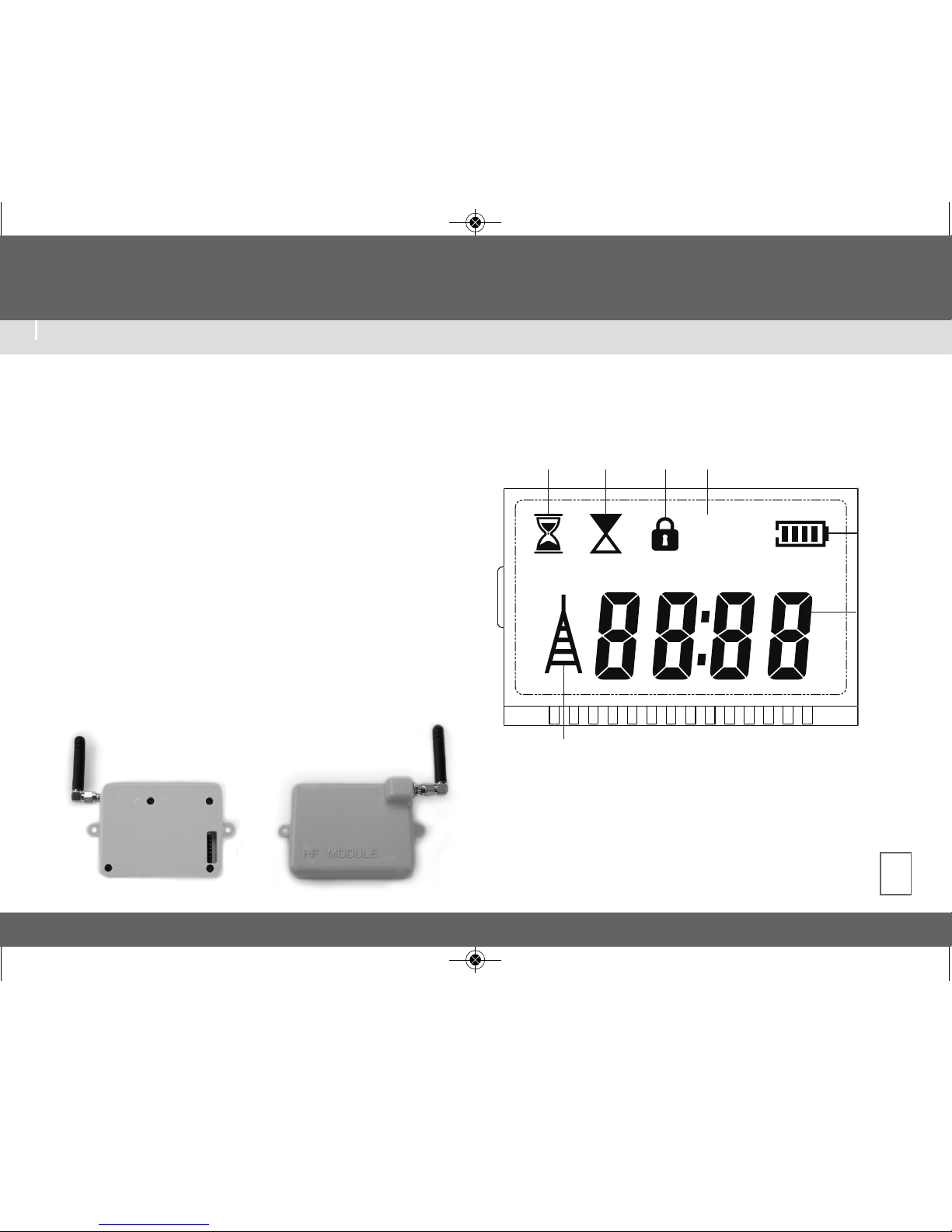
04
SYSTEM COMPONENTS
LCD DISPLAY
Owner’s Manual and Installation Instructions
RF MODULE (Receiver)
The RF Module was designed for installation within the
Pro EX 2.0 controller cabinet therefore providing permanent
placement and maximum protection. Many factors influence
operating range. Listed below are options to consider to
assure you experience the maximum range possible.
1.Do not install Pro EX 2.0 near large sources of metal such
as power meters, water pipes, and aluminum siding.
2.Do not install Pro EX 2.0 in a basement or underground location.
The higher the location the better chance of strong reception.
3.To receive maximum range in all directions, the antenna
should be pointed straight up. (vertical)
4.When operating the the remote, hold as vertical as possible
and face the direction of the receiver.
PROG
A B C
Battery
Strength
Icon
Station
Number
and
Run Time
Station
Runtime
Icon
Transmitting Icon
Active
Station
Icon
Lock
Icon
Program
Letter Icon
08-16_PROEXremote_man al_Layo t 1 6/5/17 1:08 PM Page 5

NO WIRING INSTALLATION OF THE RF MODULE
The Pro EX 2.0 Remote Control System was designed to
work right out of the box. Its “plug and play” installation
eliminates the need for complicated wiring and installation.
You’ll find no installation templets, lengthy tool list or the
need to drill any through-holes in any walls.
The RF Module receives and transmits communication
between the controller and remote. It has no wires
to connect and no batteries to replace because it is
powered by the controller once installed.
Installation is a simple three step process which only requires
a screwdriver.
STEP #1 Remove the protective pin connector cover located
at the rear of the controller face.
STEP #2 With the antenna pointing upward and to the right,
gently press the RF Module into the recess.
STEP #3 Finger tighten only using a Philips head screwdriver
the two mounting screws.
Screws
www.krain.com
05
08-16_PROEXremote_man al_Layo t 1 6/5/17 1:08 PM Page 6

06
Owner’s Manual and Installation Instructions
INSTALLING REMOTE BATTERIES
Your remote requires four
AAA alkaline batteries.
To install the batteries, remove
the Belt Clip by gently pulling either
side freeing it from the remote.
Next, slide the battery cover down
and lift to expose the battery
compartment.
Please note when installing/changing
batteries the proper orientation.
After battery installation, replace
the battery cover and slide it up to
lock it back into position.
To reinstall the Belt Clip, place
one side into position then press
the other side until it snaps into
its locking Position.
WARNING: Ris of explosion.
Potential ris if battery is replaced
with an incorrect type. Battery
must be removed and disposed
of properly.
s
!
08-16_PROEXremote_man al_Layo t 1 6/5/17 1:08 PM Page 7

POWERING UP REMOTE
Turn on the Remote by touching and holding
any button for two seconds. While the remote
powers up, it will automatically attempt to
match pin codes with any and all controllers
within signal range.
NOTES:
1.) The default pin code is 1111.
Any and all controllers within signal
range with matching pin codes will
accept remote commands.
2.) After installation we recommend
changing your code to avoid interference
with other li e controllers in the area.
See page 8.
The Remote has an auto shut off feature which
helps extend the life of the batteries. The auto
shut off or power saving feature will automatically
power down the remote after one minute from the
last touch of any button.
POWERING DOWN REMOTE
www.krain.com
07
08-16_PROEXremote_man al_Layo t 1 6/5/17 1:08 PM Page 8

08
PIN CODE
DIFFERENT PIN CODE
After powering up the remote if no
controllers with matching pins codes
are found within the signal range the
stored remote pin code will be displayed.
SAME PIN CODE
After powering up the remote, if a
controller(s) with matching pins code
is found within the signal range the
remote will display the first station
number with a run time.
NOTE: Only stations with a programmed
run time in the controller will be displayed
and operational from the remote.
CHANGING THE PIN CODE ON THE REMOTE
The Pin Code default setting (out of the box)
is factory set at 1111 but can be changed to
any combination between 0001 – 9999.
This allows a single remote the ability
to operate many controllers by simply
matching the controllers pin code.
To change the Pin Code:
• Power up the remote
OR
• Press the LEFT and RIGHT arrow
buttons simultaneously and hold
for two seconds. The pin code will
begin to flash.
1.Press the UP arrow button to
increase the flashing number value
and the DOWN arrow button to
decrease the flashing number value.
2.Press the RIGHT arrow button to advance to
the next pin number or the LEFT arrow button.
3. Once the desired pin code has been entered,
press the ON/OFF SELECT button.
Owner’s Manual and Installation Instructions
08-16_PROEXremote_man al_Layo t 1 6/5/17 1:08 PM Page 9

PIN CODE
CHANGING THE PIN CODE ON THE CONTROLLER
NOTES:
1.) To use this feature the controller must be connected
to AC power. Battery operation will not allow the user
to access this screen.
2.) The pin codes of the Controller and Remote must
match in order for the units to pair (communicate).
3.) Both units have a factory installed default pin code of
“1111”. We recommend changing the pin code to avoid
interference with other li e controllers in the vicinity.
1. Turn the controller dial to the Remote/Pin location.
2. Press the UP button one time, and the
controller displays the saved pin code.
3. Press the BACK and MANUAL START/NEXT
buttons simultaneously. One of the the digits will
flash indicating that it is ready to be changed.
www.krain.com
09
SELECT
SELECT
SELECT
START
A
PGM
pin 1 1 1 1
START
A
PGM
pin 1 1 1 1pin 1 1 1 1
08-16_PROEXremote_man al_Layo t 1 6/5/17 1:08 PM Page 10
Andere Handbücher für Pro EX 2.0
1
Inhaltsverzeichnis
Beliebte Fernbedienung Handbücher anderer Marken

Panasonic
Panasonic EUR7622KB0 Bedienungsanleitung

Bang & Olufsen
Bang & Olufsen Beo4 Bedienungsanleitung

Sunwave Tech.
Sunwave Tech. RemoteComm SRC-7000 Bedienungsanleitung

Multiplex
Multiplex PROFI TX 9 Bedienungsanleitung

One Remote
One Remote RMB4 Bedienungsanleitung

FUTABA
FUTABA 9ZAP - PART2 Bedienungsanleitung


