3
PAGE
Repair Instructions
K 350
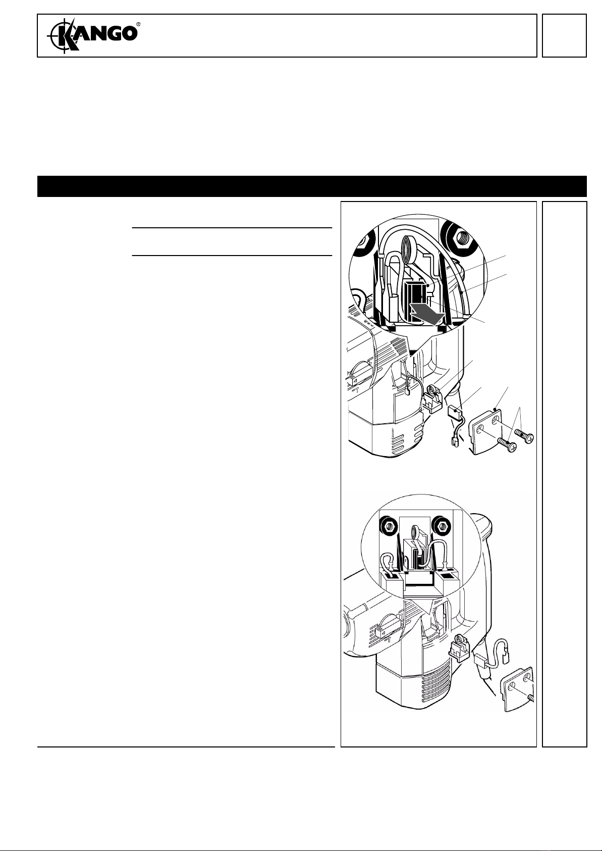
Dismantling the
spindle
(removing the
outer parts)
1Removing the rear thrust bearing assem-
bly: Lever off the spiral clip (53) with a
screwdriver. Remove the thrust bearing
assembly in the following component
parts:
– washer (58)
– thrust bearing (52)
– two compensating washers (65)
– profile ring with damper O-ring (51)
2Remove the retaining plate (45) and the
slider (43).
3Removing the spindle gear (49):
Press the spindle gear (49) using a suita-
ble sleeve against the cup springs (47) -
the spring ring (50) is released and can be
removed with pliers. Remove the spindle
gear (49).
4Remove the stop washer (48) and the cup
springs.
Dismantling the
spindle (remov-
ing the inner
locking ring)
To remove the locking ring, service tool
4.931 5990 84 is needed (see illustration 7).
1Turn the locking ring (53) with aid of serv-
ice tool, such that one end projets the
service boring by approx. 2 mm.
2Put a screwdriver through the service bor-
ing and place it under the locking ring (53).
3Move the screwdriver to and fro and at the
same time turn the locking ring with aid of
the service tool in direction of arrow. Turn
the locking ring until it is completely lev-
ered off.
4Press the locking ring from the spindle.
47 48 4950 43 45
53
50
47
49
58
5152
65
53
B
A
53