Kaval LNKFIB-H01 Bedienungsanleitung
LinkNet Satellite Unit (LSU)
RF - FIBER
Interface Modules
User Manual
Installation, Operation
And Maintenance
KAVAL WIRELESS TECHNOLOGIES
60 Gough Road
Markham, Ontario, L3R 8X7
Telephone: (888) 86-KAVAL
Web: www.kaval.com
Document #DCM000000052, Rev.5a
June 17, 2003

SatelLink zUSER MANUAL DCM000000052
Printed: 2003-06-19 16:02:58
Revision Date: 6/19/03: ii
P
PR
RO
OP
PR
RI
IE
ET
TA
AR
RY
Y
S
ST
TA
AT
TE
EM
ME
EN
NT
T
© 2000 KAVAL WIRELESS TECHNOLOGIES All rights reserved.
No part of this publication, or any software included with it may be reproduced, stored in a retrieval system,
or transmitted in any form or by any means, including photocopying, electronic, mechanical, recording or
otherwise, without the prior written permission of the copyright holder.
This document contains proprietary information of KAVAL WIRELESS TECHNOLOGIES The contents are
confidential and any disclosure to persons other than the officers, employees, agents or subcontractors of
the owner or licensee of this document, without the prior written consent of KAVAL WIRELESS
TECHNOLOGIES, is strictly prohibited.
KAVAL WIRELESS TECHNOLOGIES provides this document as is, without any warranty of any kind either
expressed or implied including, but not limited to, the implied warranties of merchantability and fitness of a
particular purpose. KAVAL WIRELESS TECHNOLOGIES may make changes or improvements in the
equipment, software, or specifications described in this document at any time and without notice. These
changes will be incorporated in new releases of this document.
This document may contain technical inaccuracies or typographical errors. KAVAL WIRELESS
TECHNOLOGIES waives responsibility for any labour, materials, or costs incurred by any person or party as
a result of using this document. KAVAL WIRELESS TECHNOLOGIES, and any of its affiliates shall not be
liable for any damages (including, but not limited to, consequential, indirect or incidental, special damages or
loss of profits or date) even if they were foreseeable and KAVAL WIRELESS TECHNOLOGIES has been
informed of their potential occurrence, arising out of or in connection with this document or its use.
T
TR
RA
AD
DE
E
M
MA
AR
RK
K
N
NO
OT
TI
IC
CE
E
This manual makes reference to trademarks that are the property of other companies. References are used
only to refer to the products or services of the trademark owners.
LSU is a trademark of KAVAL WIRELESS TECHNOLOGIES

SatelLink zUSER MANUAL DCM000000052
Printed: 2003-06-19 16:02:58
Revision Date: 6/19/03: iii
TABLE OF
CONTENTS
1. LSU MODULES ........................................ 4
OVERVIEW ............................................................. 4
Theory Of Operation......................................... 4
MODELS................................................................. 4
BLOCK DIAGRAMS .................................................. 5
LSU Head-End Module..................................... 5
LSU Remote Module ....................................... 6
CONNECTIONS ....................................................... 7
LSU Head-End Module..................................... 7
LSU Remote Module ....................................... 8
LSU Head-End to Remote Interconnects...... 10
MODULE SPECIFICATIONS ..................................... 11
REMOTE MODULE PER-CARRIER DE-RATING......... 12
OPERATION .......................................................... 13
Normal Operation ........................................... 13
Configuration .................................................. 13
LASER SAFETY ..................................................... 14
ANTENNA INSTALLATION........................................ 15

SatelLink zUSER MANUAL
Printed: 03.06.19,16:02
Revision Date:6/19/03 4
Theory Of Operation
The LSU RF to Fiber Modules provide a multi-band, multi-service link from a main
distribution center to multiple local antennae. RF Signals are distributed in runs of
three pairs of Single-Mode Fiber-Optic Distribution Lines, organized as...
Fiber Pair #1: 1.9 GHz PCS Services
Fiber Pair #2: 800 MHz Cellular Services
Fiber Pair #3: 800 MHz iDEN, Public Safety, & Paging Services
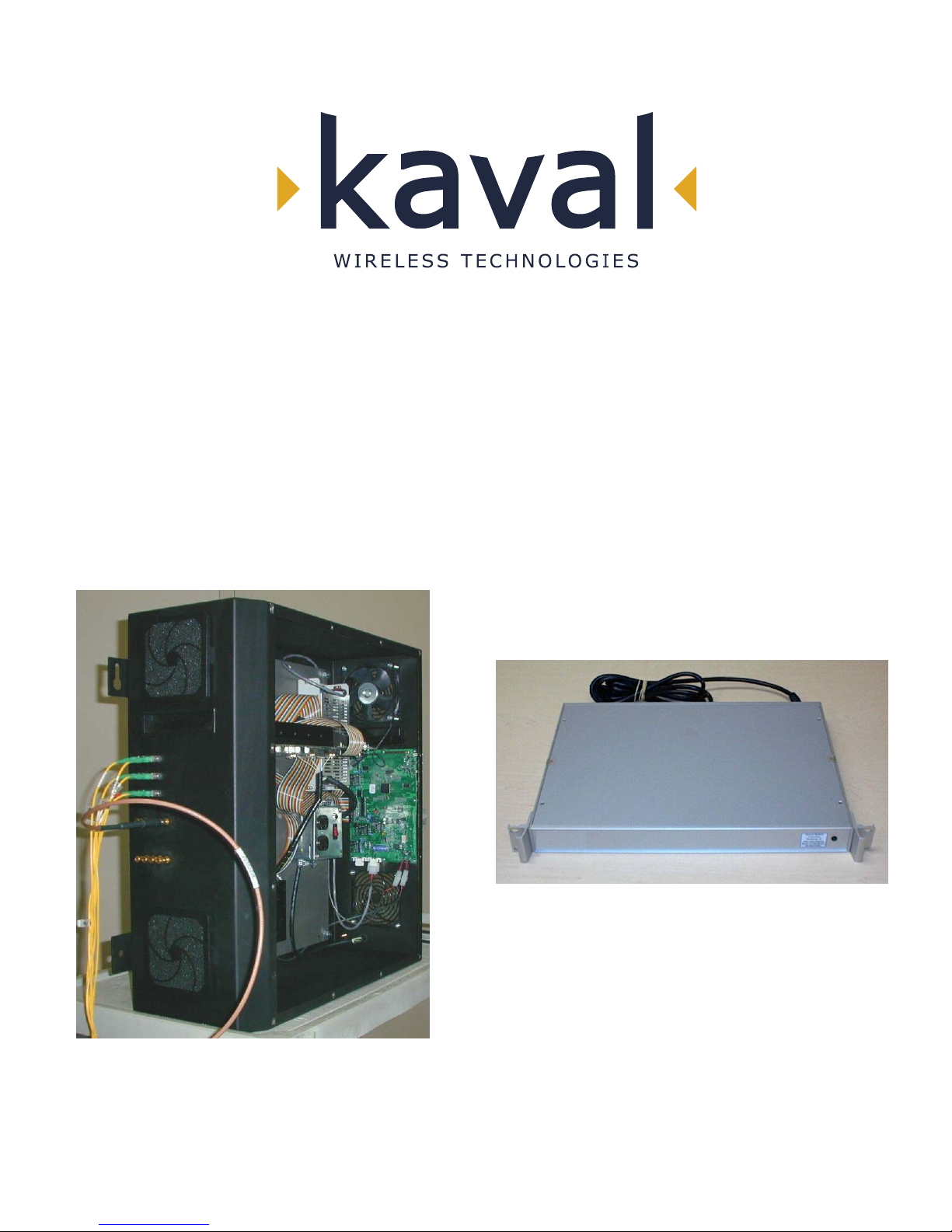
There are two models....
LSU
MODEL DESCRIPTION
LNKFIB-H01
This is a 1U high, 19" Rack-Mount Module providing low signal
level interfacing between Head-End RF Modules and Single-Mode
Fiber-Optic Distribution Lines. One is used for each of the three
Fiber Pair Groups, and can service up to four Remote Modules.
LNKFIB-R01
This is a Wall-Mounted Remote Module that connects to the Single-
Mode Fiber-Optic Distribution Lines and provides eight local
Distribution Antennae for Signal Extension.
NOTE:
With these Modules, there is always a grouping of three (3) of LNKFIB-H01's to
every four (4) LNKFIB-R01's.
1. LSU MODULES
Overview
Models

SatelLink zUSER MANUAL
Printed: 03.06.19,16:02
Revision Date:6/19/03 5
LSU Head-End Module
Block Diagrams
SMF.O. In
SM F.O. Out
(P IN Di o de s )
(Las ers )
Power Supply
Mon i tor s
FO Laser and PIN Diode
120 / 240 VAC
120/240 VAC Fault Relay
PreAmp
Laser Diode
PreAmps
RF Out #1
RF Out #2
RF Out #3
RF Out #4
RF Input

SatelLink zUSER MANUAL
Printed: 03.06.19,16:02
Revision Date:6/19/03 6
LSU Remote Module
SM F.O. In
SM F.O. Out
(PIN
(Lasers
Fou
r
A
ntenna
Ports
1.9GHz
Cellular
Power Suppl
y
Monitors
& Power
Loose
Couplers
RF Monito
r
2 RF Ports to
Ports
FO Current
120 / 240
Micro-
Circuit
r
120/240
CAN RS232
To Head- To PC
Green Power On
Red Fault LED
Fault
24 VDC
PreAmp
IDEN &
PreAm
p
1.9GHz
Cellular
IDEN &
869-894 MHz
1.9 GHz
851-869 MHz
1.8 GHz
824-849 MHz
806-824 MHz
Notch 851+
Notch 894-
928-941 MHz
899-902 MHz
A
ntennae on
A
lternate
1.9GHz
800-900MHz

SatelLink zUSER MANUAL
Printed: 03.06.19,16:02
Revision Date:6/19/03 7
LSU Head-End Module
The Head-End has one Downlink RF Input providing the signal for four Downlink
Optical Outputs, thus each Head-End Module services one and only one of the three
Fiber-Pairs (PCS, Cellular, or iDEN/Trunking).
Connections
Head-End Connections
SC/APC SingleMode Fiber-Optic & SMA RF Connectors
AC Power Cord
Downlink Optical Outputs
TX1 TX2 TX3 TX4 RX1 RX2 RX3 RX4
Uplink Optical Inputs
TX In RX1 RX2 RX3 RX4
Downlink RF Input
Uplink RF Outputs

SatelLink zUSER MANUAL
Printed: 03.06.19,16:02
Revision Date:6/19/03 8
LSU Remote Module
Antenna Port Connections
Four Direct Antenna Connections
Two Expansion Antenna Connections
Uplink Sampler Port Downlink Sampler Port
SMA Connections
The Remote Module has 8 SMA RF Connections..
Main Antenna Ports (4): Used to connect to four identical distributed indoor
antenna systems.
Expansion Antenna Ports (2): Connected to a secondary location via 2 of two-way
combiners, and in turn provide connections to four
more identical distributed indoor antenna systems.
Sampler Ports (2): Optionally allow an operator to monitor the Uplink
and Downlink RF activity at approx. 30dB below the
actual levels.

SatelLink zUSER MANUAL
Printed: 03.06.19,16:02
Revision Date:6/19/03 9
Fiber Optic Port Connections
PCS Uplink Optical Output PCS Downlink Optical Input
Cellular Uplink Optical Output
iDEN/Paging Uplink Optical Output
Cellular Downlink Optical Input
iDEN/Paging Downlink Optical Input
SC/APC SingleMode Fiber-Optic Connectors
The Remote Module has 6 SC/APC Single-Mode Fiber-Optic Connections for
cabling to the Head-End...
PCS Up & Downlink: Used for the PCS Fiber-Optic Pair connection to the
Head-End.
Cellular Up & Downlink: Used for the Cellular Fiber-Optic Pair connection to
the Head-End.
iDEN/Paging Up & Downlink: Used for the combined iDEN / Paging Fiber-Optic
Pair connection to the Head-End.

SatelLink zUSER MANUAL
Printed: 03.06.19,16:02
Revision Date:6/19/03 10
LSU Head-End to Remote Interconnects
The Single-Mode Fiber-Optic interconnections between the Head-End and Remote
Modules are based upon the Head-Ends being organized on a "per Fiber-Pair"
system. This fundamentally means that an installation requires three Head-Ends for
every four Remote Modules. It also means that if you have a fully optimized system
with all Head-End ports in use, and you add one more Remote Module, then another
three Head-End Modules are required.
Head-End to Remote Fiber-Optic Connections
Groupings of 3 Head-Ends to every 4 Remotes
PCS Head-End
Cell Head-End
Head-End
iDEN / Paging
Remote Module
Remote Modules
To 3 More
Remote Modules
To 3 More
Remote Modules
To 3 More
Dieses Handbuch passt für folgende Modelle
2
Inhaltsverzeichnis
Andere Kaval Steuereinheit Handbücher


Beliebte Steuereinheit Handbücher anderer Marken

Festo
Festo Compact Performance CP-FB6-E Stücklistenhandbuch

Elo TouchSystems
Elo TouchSystems DMS-SA19P-EXTME Bedienungsanleitung

JS Automation
JS Automation MPC3034A Bedienungsanleitung

JAUDT
JAUDT SW GII 6406 Series Kurzanleitung

Spektrum
Spektrum Air Module System Bedienungsanleitung

BOC Edwards
BOC Edwards Q Series Bedienungsanleitung


