KEENCUT Evolution Bedienungsanleitung

Instruction Manual
Provided By
http://www.MyBinding.com
http://www.MyBindingBlog.com
Foster KeenCut
Evolution Rotary
Cutter

Evolution
INSTRUCTIONS
Thank you for choosing the Keencut Evolution.
Every effort has been made to bring you a superbly built
product with the promise of many years of good service.
Keencut – the world’s finest cutting machines
Keencut Limited, Baird Road, Willowbrook Industrial Estate, Corby, Northants, ENGLAND NN17 5ZA.
Telephone: 01536 263158 Facsimile: 01536 204227 E-mail: info@keencut.co.uk
www.keencut.co.uk

1 Contents
2 Before you Start
2.1 Checking the bench for installation
2.2 Check and adjust worktop flatness
The fixing bracket jacking screws
2.2 Setting out the fixing brackets
3 Setting up
3.1 Fitting the Lift Handles (remove strapping)
3.2 Adjust for groove alignment
3.3 Positioning the Base Fixing brackets
3.4 Check and adjust the clamping
3.5 Adjust for flatness and grip - paper test
3.6 Build up bench surface
4 Operation
4.1 About the blades - inserting and setting the blade - blade
depth adjuster
4.2 Inserting the blade and setting the depth
4.3 Inserting and aligning the material
4.4 Cutting heavy and lightweight materials
4.5 Using the textile cutting attachment
5 Maintenance
5.1 Cleaning and lubrication - (warning note)
Adjusting the cutting head sliding bearings.
1
Contents
1

2.1 Before you start 2.1
Overall length of cutter
Worktop
9.5cm
Overall length of cutter
Worktop
15cm 24.5cm
9.5cm
●Evolution 160cm (64”) overall length 177.5cm (69.9”) 4 base fixing brackets
●Evolution 210cm (84”) overall length 227.5cm (89.6”) 5 base fixing brackets
●Evolution 260cm (104”) overall length 277.5cm (109.25”) 6 base fixing brackets
●Evolution 10cm (124”) overall length 27.5cm (128.9”) 7 base fixing brackets
●Evolution 60cm (144”) overall length 77.5cm (148.6”) 8 base fixing brackets
✍
✍
CHECKING THE BENCH FOR INSTALLATION
■Do not remove the Evolution from its packing crate until the instruction below
says so.
■As part of the installation there are a number of checks/adjustments to be made,
it is essential that time is put aside to carry these out properly or the overall
performance of the cutter will be affected.
The Evolution Cutter Bar can be fixed to an existing work bench or to a KEENCUT
bench, the bench must be stable enough so that it does not flex when pushed from the
side and the worktop made from a robust material, firmly fixed to the frame and ideally
flat to within mm (1/8”).
The cutter can be fixed along the edge of the bench or slightly inboard but do not mount
the cutter too far away from the edge as it could become difficult or uncomfortable to
operate if you have to lean too far over when making a cut.
If the cutter is to be mounted along the edge of the bench draw a line 9.5cm in from the
edge of the worktop and the length of the cutter as listed below.
Should you want to use the cutter, say, 15cm in from the edge draw the line
15 + 9.5 = 24.5cm from the edge of the worktop.
2.2 Before you start 2.2
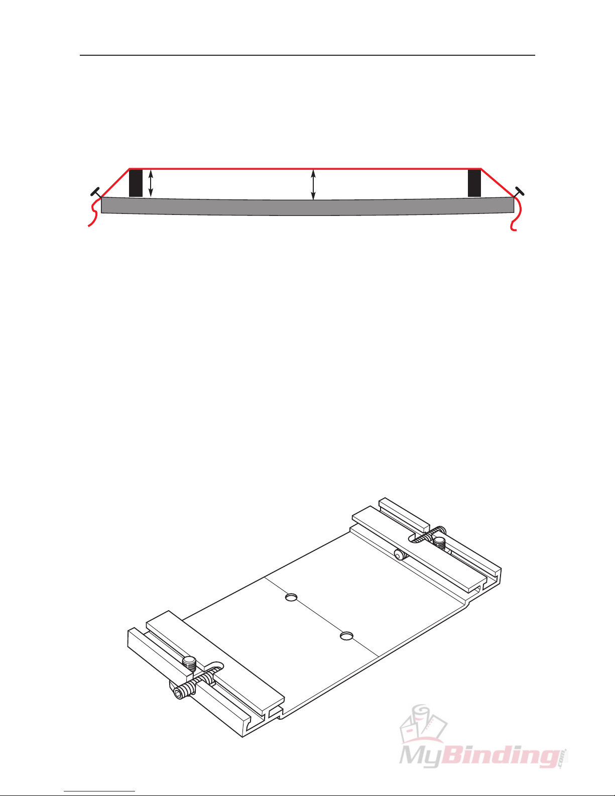
CHECK & ADJUST THE WORKTOP FLATNESS
Check the flatness of the worktop by stretching a thin piece of strong thread between two
blocks (of the same height) approximately over the line. Measure the highest and lowest
part of the worktop under the thread, the difference between the two measurements
should be no more than mm (1/8”).
?mm ?±mm ✓
worktop
➤
➤
If it is....
Adjust the surface flatness by adding packing pieces made from 2- mm (1/16”) thick
rigid material such as PVC Foamboard, under the Base Mounting Brackets as they are
installed (next section).
THE FIXING BRACKET JACKING SCREWS
The Base Fixing Brackets are designed to hold the Base of the cutter firmly in position
and provide a means to adjust the cutter Base for both flatness and alignment of the
cutting groove. Check the Jacking Screws are screwed up finger tight as shown before
fitting the Brackets to the worktop.

➤
➤
9.7cm 42cm
2.3 Before you start 2.3
SETTING OUT THE FIXING BRACKETS
Place a Bracket 9.7cm ( .8”) in from the left hand end of the pencil line as shown,
ensure the groove along the centre of the Bracket is aligned with the pencil line and
screw it down to the worktop with two of the short wood screws provided. Fix the
remaining brackets along the line leaving a 42cm (16.5”) gap between them. When
screwing them all down firmly again ensure the groove in the centre of the bracket
aligns with the pencil line.
42cm 42cm42cm9.7cm
●Example:
Evolution 160, 4 base fixing brackets
Evolution 160cm (64”)

Remove the clear plastic stretch-wrap bands.
2.4 Before you start 2.4
Lift the Evolution cutter bar from its crate but do not remove the clear plastic stretch-wrap
bands holding the base to the cutter bar. Place the Evolution centrally on the Brackets
and manoeuvre it until the base is located properly down on each of the Brackets.
Tighten the grub screws at the back of each of the Brackets by 4 full turns and then
tighten the front grub screws fully (approx 4- 6 turns).
➤
➤

3.1 Setting Up 3.1
FITTING THE LIFTING HANDLES
Fix the Lift & Hold Handles at each end of the cutter bar, the machined out section of
the fork faces to the centre of the machine and is inserted into place at an angle as
shown. Once in position straighten so that the rectangular feature on the handle fits into
its mating hole in the adjacent black steel part.
Tighten firmly, the clamping screw using the 5mm Allen key provided.

3.2 Setting Up 3.2
CHECK & ADJUST THE CUTTING GROOVE ALIGNMENT
Check the back of the cutting groove in the Base is in line with the edge of the cutter bar
so that a blade in the cutting head will run the full length of the machine without touching
either side of the groove, if it does not....
Adjust the straightness of the Base by adjusting the back and front grub screws in the
Base Fixing Brackets:
To push the groove away from you, loosen the
back grub screw in the adjacent Bracket/s and
then tighten the front grub screw by the same
amount, this slightly distorts the Base and aligns
the groove to the cutter bar. You may find that if
a part of the groove needs to move by a large
amount the neighbouring Brackets may also need
to be adjusted. After making an adjustment pull
the lift and hold handles towards you to lift the
cutter bar and lower it again to re-settle it, check
and adjust further if required.
To pull the groove towards you the procedure is the same as above, but loosen the front
grub screw and tighten the back grub screw.
BACK
FRONT
? = ?
? < ?
✓
✗

3.3 Setting Up 3.3
Place two of the long wood screws in the front holes of the Fixed Arms (A) and screw
then in but do not tighten them. Loosen the four Allen head screws (B) joining the Fixed
Arms to the Base by one turn then fully tighten screws (A).
To enable the table surface to be cleared of the cutter bar when it is required for other
work the whole cutter bar can be lifted and swung on its hinges towards you so that it
hangs down along the edge of the work bench (this also helps with cleaning).
x4
x2
NOTE: Be particularly careful with the longer versions of cutter as they are very heavy.
Carefully swing the cutter bar down now and place the remaining two long wood screws
(C) into the back two holes of the Fixed Arms and tighten. Return the cutter bar to its
working position.
x2
Inhaltsverzeichnis


