
Kingspan TMS300 MULTI-TANK CS Betriebsanleitung

kingspanenergymanagement.com
Smart Monitoring
TMS300 CS
Multi-Tank
User and
Installation
Manual
ENG

TMS300 CS Multi-Tank – User Manual
2
Contents
1. Specication
1.1. Dimensions
1.2. Electrical and environmental specication
1.3. Inputs
1.4. Outputs
1.5. Relay outputs
1.6. Connectivity
1.7. Sensor
1.8. Additional equipment
2. Safety precautions
3. Mounting
4. Operation manual
4.1. Tanks
4.2. Network
4.3. LCD contrast
4.4. LCD backlight ON/OFF
4.5. Buzzer ON/OFF
4.6. Webserver password
4.7. Default setting
4.8. 4-20 mA output
5. Web server connection
5.1. Network connection
5.2. Direct connection
5.3. Wi-Fi connection (USB Wi-Fi adapter required)
6. Conguring sensor and tank details
6.1. Channel wizard
6.2. Connectivity wizard
6.3. Relays
6.4. Setup summary
6.5. Real-time data
7. Software upgrade by USB cable
8. Wall mount template
4
4
4
4
4
4
5
5
5
6
7
9
10
10
10
11
11
11
11
11
12
12
12
13
14
14
15
16
17
17
18
19
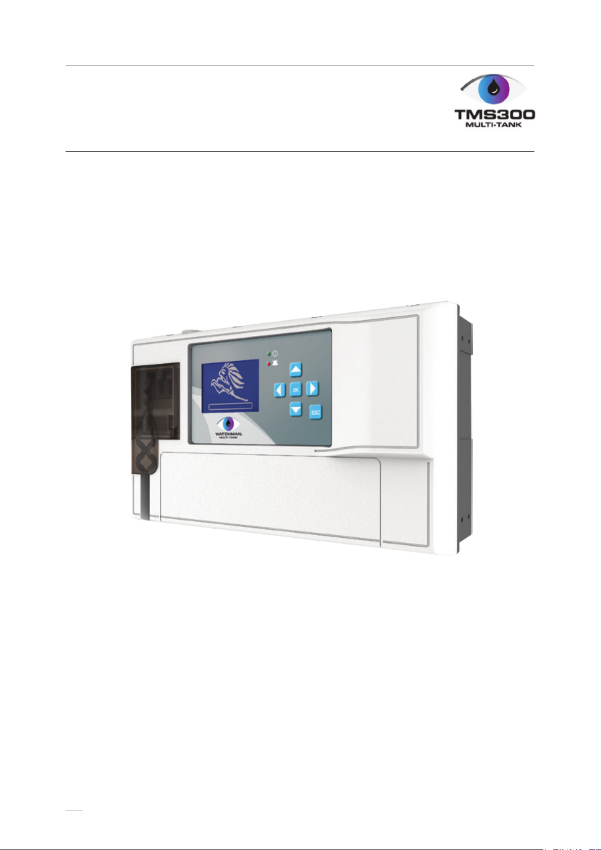
· Tank levels via Local screen, embedded
webserver, App, online portal or emails
· Multi tank level measurement (wireless and
wired, up to 18 channels)
· Connectivity options via Local Network,
GSM (2G/3G) or Internet
· Volt free relay outputs for overl/leak/low level
alarms/sudden drop
· CE certicated
· Historical levels
· Levels (litres, percentage, mm)
· Alarms (sensor disconnection, leak, high and
low alarms, email alerts)
· Dry contact inputs, up to 6
Summary of features
3
TMS300 CS Multi-Tank – User Manual

1. Specication
1.1. Dimensions
4
· Width: 300 mm
· Height: 180 mm
· Depth: 100 mm
· Supply voltage: 110-240 V AC or 12-24 V DC
· Max input power: 24 VA
Note: The information supplied in this manual is for guidance only – no part of this may be used for
any agreement, whether express or implied, or to form any contract.
TMS300 CS Multi-Tank – User Manual
· Optional wireless module
- 433 MHz
- Compatible with Watchman®Sonic
transmitter family
· 6 channels, 4-20 mA with internal 12 V DC
power supply
- Compatible with any 4-20 mA sensor i.e.
relative pressure, ultrasonic etc.
· 4-20 mA output (only with RF module)
Note: The alarm relays are 2 contact arrangements which are isolated (volt-free). These relays may be
used to trigger an external bell, warning lamp or digital communicator (telephone dialler).
1.5. Relay outputs
1.4. Outputs
1.3. Inputs
· Operating temperature: 0˚C - 40˚C
· Relay’s max switching current: 5 A
1.2. Electrical and environmental specication

· TP Link Wi-Fi adapter· RF module
1.8. Additional equipment
1.5. Relay outputs
5
TMS300 CS Multi-Tank – User Manual
Number of relays
Contact mechanism
Max. switching voltage
Max switching current
Resistive load
2
DPCO
250 V AC, 220 V DC
5 A
CH1
+ - CH2
+ - CH3
+ - CH4
+ - CH5
+ - CH6
+ - 12-24 V DC
+ GND
Relay 1 Relay 2
· Connect Sensor
- GSM 2G/3G
- Internet (port forwarding required)
· Embedded Web Server
- direct connection via ethernet cable
- local network
- Internet (port forwarding required)
- Wi-Fi network (USB Wi-Fi adaptor required)
1.6. Connectivity
1.7. Sensor
· Any 4-20 mA sensor
· Watchman®Sonic - 003963
· Watchman®Sonic EU 004644
· Watchman®Sonic Alarm - 004030
· Watchman®Sonic Alarm EU 004645
· Watchman®Sonic Plus - 002893
· Watchman®Sonic Plus EU 007041
TMS300 is compatible with:
· Watchman®LT (24 V DC external power supply
required) – 026769
· Watchman®Sonic 4-20 mA waveguide - 019052
· Watchman®Sonic Waveguide EU - 019369
· Watchman®Alarm Waveguide EU - 019371
· 4-20 mA pressure sensor - 004035

2. Safety precautions
6
Installation
Note: This installation procedure is for guidance only, and its suitability should be veried by the installer.
The following safety precautions are strongly recommended:
· Before attempting to install and operate the unit, read the instruction and installation manual
carefully.
· Installation and any maintenance should only be carried out by suitably qualied personnel.
· It is recommended that the unit be connected to the mains supply via a suitably rated isolating switch.
Warning! When the unit is connected to the mains supply and the cover is open, the circuits at
mains voltage will be exposed. Therefore when installing the unit, ensure all required connections
(including battery connected, if included), are made and covers replaced before turning on the
mains supply. Ensure that all the connections made are secure. If any maintenance work e.g.
installing a new battery, is required ensure that the unit is isolated from the mains supply before
removing the cover. Never leave the unit unattended if the cover has been removed and the mains
supply is connected.
· Do not exceed unit ratings as shown on the ratings label.
· It is advisable to route mains cables away from low voltage or sensor cables.
Note: For viewing comfort, the unit should be positioned at eye level. The ideal operating temperature
of the unit is (0oC to +40oC). It is always good practice to keep electronic equipment away from cold,
heat and electrical plant, as extremes of temperature may reduce the lifetime of the device, and
heavy electrical loads, switches, relays or contactors too close to the device may cause electrical
and electro-magnetic interference when switched on or o.
TMS300 CS Multi-Tank – User Manual

3. Mounting
7
Panel mount (required panel mount kit)
· Cut a hole in the panel with the described
dimensions (page 20)
· Remove the Front Lid unscrewing two screws
· Disconnect the modules
· Separate the front cover by unscrewing two
screws
· Remove the required knock outs from Back Box
for the cables to pass through (always separate
front cover before removing the knock outs)
· Attach the Panelmount Seal, ensure that it is
on the right position
· Insert the Back Box into the panel cut out
· Attach the four panel mount xing clips
(supplied), to the four studs at either side of
the unit (page 20)
· Tighten the four Panelmount Fixing Screws
· Insert the cable glands
· Pass the cables through the glands
· Mount the Front Cover on the Back Box
· Insert the modules
· Connect the power supply cable and sensors
· Tighten the cable glands
· Mount the front lid
· Operating temperature: 0˚C - 40˚C
· Relay’s max switching current: 5 A
Wall mount
· Drill four holes in the wall, according to the
template and insert the wall plugs
· Remove the Front Lid by unscrewing two screws
· Disconnect the modules
· Separate the front cover by unscrewing two
screws
· Remove the required knock outs from Back Box
for the cables to pass through (always separate
front cover before removing the knock outs)
· Insert the cable glands
· Screw in the Back Box to the wall
· Pass the cables through the glands
· Mount the Front Cover on the Back Box
· Insert the modules
· Connect the power supply cable and sensors
· Tighten the cable glands
· Mount the front lid
TMS300 CS Multi-Tank – User Manual
Note: This device should be properly earthed. Flexible wires simplify connection to the terminals.
All connections should be secure and adequately tightened. It is good practice to keep mains cables
away from sensor cables and other low voltage signal cables.
· Supply voltage: 110-240 V AC or 12-24 V DC
· Max input power: 24 V A

3. Mounting
8
TMS300 CS Multi-Tank – User Manual
Template - page 20

4. Operation manual
9
TMS300 CS Multi-Tank – User Manual
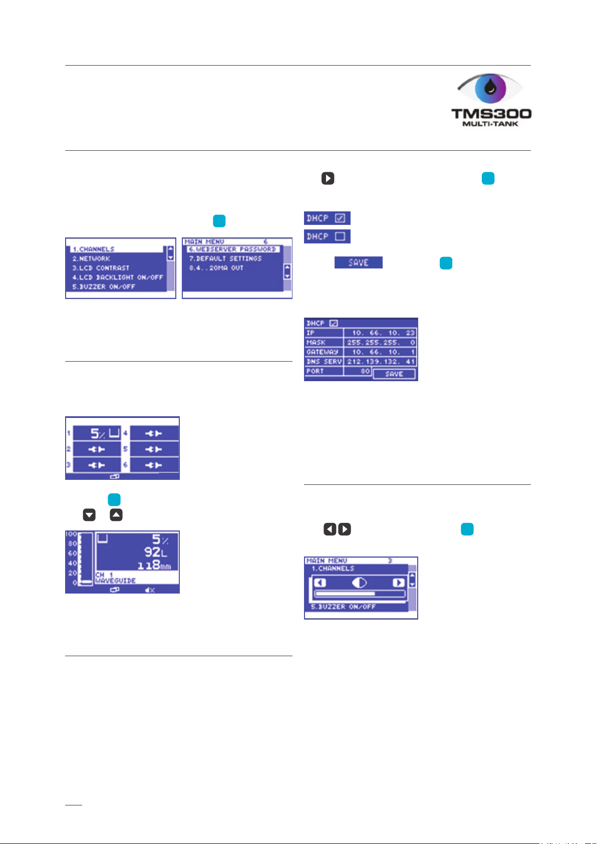
In order to fully understand the operation
of the unit, this section should be read carefully.
Power ON/OFF indicator
Alarm Triggered Indicator
Max. Volume Alarm Hard
Max. Volume Alarm Soft (blinking icon)
Min. Volume Alarm Hard
Min. Volume Alarm Soft (blinking icon)
LAN cable connected and IP obtained
GSM/GPRS signal strength
Buzzer OFF/Alarm muted
Channel OFF
Sensor disconnection
4. Operation manual
TMS300 CS Multi-Tank – User Manual
To set Automatic Network Conguration, use
the key to select DHCP and use the
key to select or deselect this option.
Indicates that the DHCP is OFF.
Indicates that the DHCP is ON.
Select and use the key to save the
settings.
It can take few minutes to save new settings.
To obtain the IP address please contact with
your Network Administrator.
This screen allows user to adjust the LCD contrast.
Use to adjust and press the key
to conrm.
Main menu
This screen allows user to choose any options
available.
To back to Main menu press the key.
These screens allow user to view all the sensor
status for each channel, e.g. Level, Disconnection,
Alarms.
Press the key to reveal the channel view,
use or to change between channels.
This screen allows user to set up the Network
connection. User can choose DHCP option
or manually enter the IP address.
OK
OK
OK
ESC
OK
4.1. Tanks
4.2. Network
4.3. LCD contrast
10
Andere Handbücher für TMS300 MULTI-TANK CS
1
Inhaltsverzeichnis
Beliebte Steuereinheit Handbücher anderer Marken

Festo
Festo Compact Performance CP-FB6-E Stücklistenhandbuch

Elo TouchSystems
Elo TouchSystems DMS-SA19P-EXTME Bedienungsanleitung

JS Automation
JS Automation MPC3034A Bedienungsanleitung

JAUDT
JAUDT SW GII 6406 Series Kurzanleitung

Spektrum
Spektrum Air Module System Bedienungsanleitung

BOC Edwards
BOC Edwards Q Series Bedienungsanleitung


