
KIPI 24 kW Bedienungsanleitung

1
Manual
Name: KIPI air heater
Models:
24 kW,
30 kW,
50 kW,
70 kW,
100 kW,
150 kW,
200 kW,
250 kW
BTI GUMKOWSKI Sp. z o.o. Sp.k.
ul. Obornicka 71, 62-002 Suchy Las
+48 61-811-70-37
update 15-01- 2021

2
Symbols:
Warning. Indicates that the user must read with an operating manual where you
can find important information such as cautions and warnings that cannot be
included for various reasons on the medical device.
Moving parts symbol. The moving parts symbol indicates areas of the analyzer
where moving parts may cause physical injury. Do not operate the analyzer with
open covers.
Warning under voltage.
Hot surfaces, do not touch.
Follow the instructions for use. Indicates the need for the user to read the
instruction manual.

3
Table of Contents
1. General information ...................................................... Błąd! Nie zdefiniowano zakładki.
2. Description and purpose of the device .......................... Błąd! Nie zdefiniowano zakładki.
3. Fuel specification .......................................................... Błąd! Nie zdefiniowano zakładki.
4. Construction of the heater ............................................. Błąd! Nie zdefiniowano zakładki.
5. Components .................................................................. Błąd! Nie zdefiniowano zakładki.
6. Safety systems used in the heater ...................................................................................... 10
7. Transport ........................................................................................................................... 14
8. Assembly ........................................................................................................................... 15
8.1. The sequence of assembly works .......................... Błąd! Nie zdefiniowano zakładki.
9. Installation ..................................................................... Błąd! Nie zdefiniowano zakładki.
9.1. Connecting the heater to the electrical system .......................................................... 21
9.2. Connecting the heater to the chimney installation . Błąd! Nie zdefiniowano zakładki.
9.3. Verification of the ventilation system ................... Błąd! Nie zdefiniowano zakładki.
10. Running ..................................................................... Błąd! Nie zdefiniowano zakładki.
10.1. Preparing the device for the first start ................ Błąd! Nie zdefiniowano zakładki.
10.2. The first start of the burner. ................................................................................... 25
10.2.1. The sequence of works related to the first start-up ........ Błąd! Nie zdefiniowano
zakładki.
11. Exploitation ............................................................... Błąd! Nie zdefiniowano zakładki.
11.1. Safe operation conditions ................................... Błąd! Nie zdefiniowano zakładki.
11.2. Heater maintenance ............................................... Błąd! Nie zdefiniowano zakładki.
11.3. Wytyczne ogólne ............................................... Błąd! Nie zdefiniowano zakładki.
11.4. General guidelines ............................................. Błąd! Nie zdefiniowano zakładki.
11.5. Cleaning the combustion chamber ..................... Błąd! Nie zdefiniowano zakładki.
11.6. Cleaning the hatch .............................................. Błąd! Nie zdefiniowano zakładki.
11.7. Cleaning the ash pan .......................................... Błąd! Nie zdefiniowano zakładki.
12. Technical data ........................................................... Błąd! Nie zdefiniowano zakładki.
12.1. Models of heaters, overall dimensions ............... Błąd! Nie zdefiniowano zakładki.
12.2. Device identification .......................................... Błąd! Nie zdefiniowano zakładki.
12.3. Electrical diagram of the ecoTOUCH 920P regulator ....... Błąd! Nie zdefiniowano
zakładki.
12.4. Technical parameters of heaters ......................... Błąd! Nie zdefiniowano zakładki.
13. EC declaration of conformity ........................................................................................ 42
14. List of common faults ............................................... Błąd! Nie zdefiniowano zakładki.
15. Spare parts list ........................................................... Błąd! Nie zdefiniowano zakładki.
16. Terms of warranty ..................................................... Błąd! Nie zdefiniowano zakładki.
17. Attachments: .................................................................................................................. 53
17.1. Warranty - first run - a copy to be sent along with the GDPR consent clause ...... 53
17.2. Warranty - first start of the heater ...................... Błąd! Nie zdefiniowano zakładki.
17.3. Warranty - annual inspection ............................. Błąd! Nie zdefiniowano zakładki.
17.4. Warranty - two-year inspection.......................... Błąd! Nie zdefiniowano zakładki.
17.5. Repairs ............................................................... Błąd! Nie zdefiniowano zakładki.

4
1. General information
This manual for the KIPI air heater, which is automatically fueled with solid fuel, pellet,
constitutes the Technical and Operation Documentation. Document is an integral part of the
device 1 . Detailed analysis of the instructions will allow the user to learn about the structure of
the device, installation and operation tips. Respecting the manufacturer's instructions in the
manual will ensure correct and safe operation of the heater.
Connection and first running of the heater, as well as possible installation of the
burner
must be performed by an authorized and qualified service center
The manufacturer is not responsible for any damage caused as a result
defective installation, inconsistent with these instructions.
Works related to the installation and use of the heater should begin with:
- checking the heater's housing in case of damage caused by transport,
- verification of the content of the delivery, both in terms of the presence of all
components and their compliance (comparison with nameplates),
- getting acquainted with the operating instructions for the heater, burner and regulator.
The KIPI air heater may only be used for its intended purpose.Any other use will be considered
improper by the manufacturer and dangerous. The heater is an integral part of the ROTARY
KIPI burner and the regulatorecoMax 920 TOUCH. The heater and its components are under
warranty. Specific warranty conditions are given by the manufacturer in this manual, with
warranty card included.
The manufacturer is not liable for damages resulting from the selection of
others
components than those included in the heater kit - in particular another burner,
feeder or regulator.
The manufacturer allows the use of a different type of container than the suggested one

5
KIPI tank, but minimum feeder capacity is maintained (indicated in the burner operating man-
ual).The heater operating manual provides general information about the burner and regulator.
Detailed information on these components has been attached.
In the event of a breakdown or incorrect operation of the device, turn it off
immediately and disconnect the electrical supply. Any attempts to repair it yourself
will break manufacturer's warranty conditions. Any repairs on the heater and its components
should be performed by the manufacturer's authorized service, using original spare parts.
1. Description and purpose of the device
The KIPI air heater is a heat generator powered automatically with solid fuel, pellets. The
device has been designed for internal use to heat the air. The principle of operation is based on
use forced air circulation, which is provided by a centrifugal blower fan. The air stream passing
through the heater absorbs heat energy through circulations near the heat source. As a result,
the air leaves the heater at elevated temperature (ryc. 1.) .
The heat is generated as a consequence of burning pellets in the combustion chamber. By
means of a centrifugal blowing fan mounted in the lower part device, air is blown into the
device. Air is taken in directly from the room with the heater 3 . The heater uses only fresh air,
or a mixture of fresh air and air returning from heated rooms.
The heat energy of exhaust fumes is transferred to the injected air through the process natural
and forced convection. Air and fumes are separated in airtight channels, as a result there is no
pollution of the heated air. After losing heat energy, exhaust fumes are removed through a duct
connected to the chimney system. The diameter of the chimney is important, which must be
large enough to provide effective exhaust gas removal. Ash, created as a result of burning, is
discharged to the ash pan drawer from where it can be removed easily (see cleaning the ash
pan). Heat is transferred through adjustable air outlet duct (located in the upper part of the
heater), distributing air directly to the sides or to other rooms through supply ducts equipped
with dampers.
After reaching the required air temperature in the room, the heater when heating one room:
using a thermostat - it will turn off,
not using the thermostat - it will continue to work,
when heating several rooms:

6
using a thermostat in each of them - it will turn off,
when using a thermostat in several rooms - dampers
installed on distribution ducts to these rooms will remain closed, at the same time the heater
will continue to heat rooms without thermostats,
without using the thermostat, in any of the rooms - it will continue the work.
Ryc. 1. Diagram of air flow through the heater (hot – read, blue – cold air)

7
1. Fuel specification
The burner, which is an integral part of the air heater, is designed to burn wood biomass in
the form of pellets. Recommended for best performance the use of certified pellets meeting the
following quality requirements (Table 1).
Fraction
granules
Diameter [mm]
6±1,8±1
Length [mm]
3,15 ÷ 40
Dust content [%]
≤ 1
Bulk density [kg / m3]
≥ 600
Moisture [%]
≤ 10
Calorific value [MJ / kg]
16,5÷19
Ash [%]
≤ 0,7
Tab. 1. Quality requirements of pellets intended to power the heater.
In case of changing the fuel batch it is necessary to perform the "feeder test".
This action is important for the optimal operation of the heater. When refilling the fuel
in the tank, particular attention should be paid to undesirable elements in the form of mechanical
impurities, e.g. rock fragments. Any solid contamination, regardless of its size, may damage
the heater, including the pellet feeder, burner or ash removal system, thus leading to the failure
of the entire device..
The manufacturer is not responsible for any resulting damagefrom
failure to follow the above recommendations.
2. Construction of the heater
The KIPI air heater consists of the following components
(see Table 2, Fig. 2).
name of the element
marking
Counterflow exchanger
Combustion chamber
A1

8
Flame tubes of the 2nd line
A2
Reversing chamber
A3
Flame tubes 3 pass
A4
Exhaust outlet chamber
A5
Flue
A6
Ash removal system
Ash removal spiral
B1
Gear motor
B2
Ash removal pipe
B3
Cleaning
Rear cleanout cover
C1
Door
C2
Ash container
C3
Ash pan cover
C4
Insulation
Heater thermal insulation
D
Accessories
Torch
E1
Blower fan
E2
Air outlet elbow
E3
920ecoMAX driver panel
E4
920ecoMAX driver module
E5
Burner thermal insulation
E6
Mounting flange
E7
Tab. 2. KIPI air heater components.

9
Dig. 2. Construction of the KIPI air heater.
3. Component parts
The heater is supplied as a complete air heater kit (see Figure 3).
The set consists of::
E7
E6
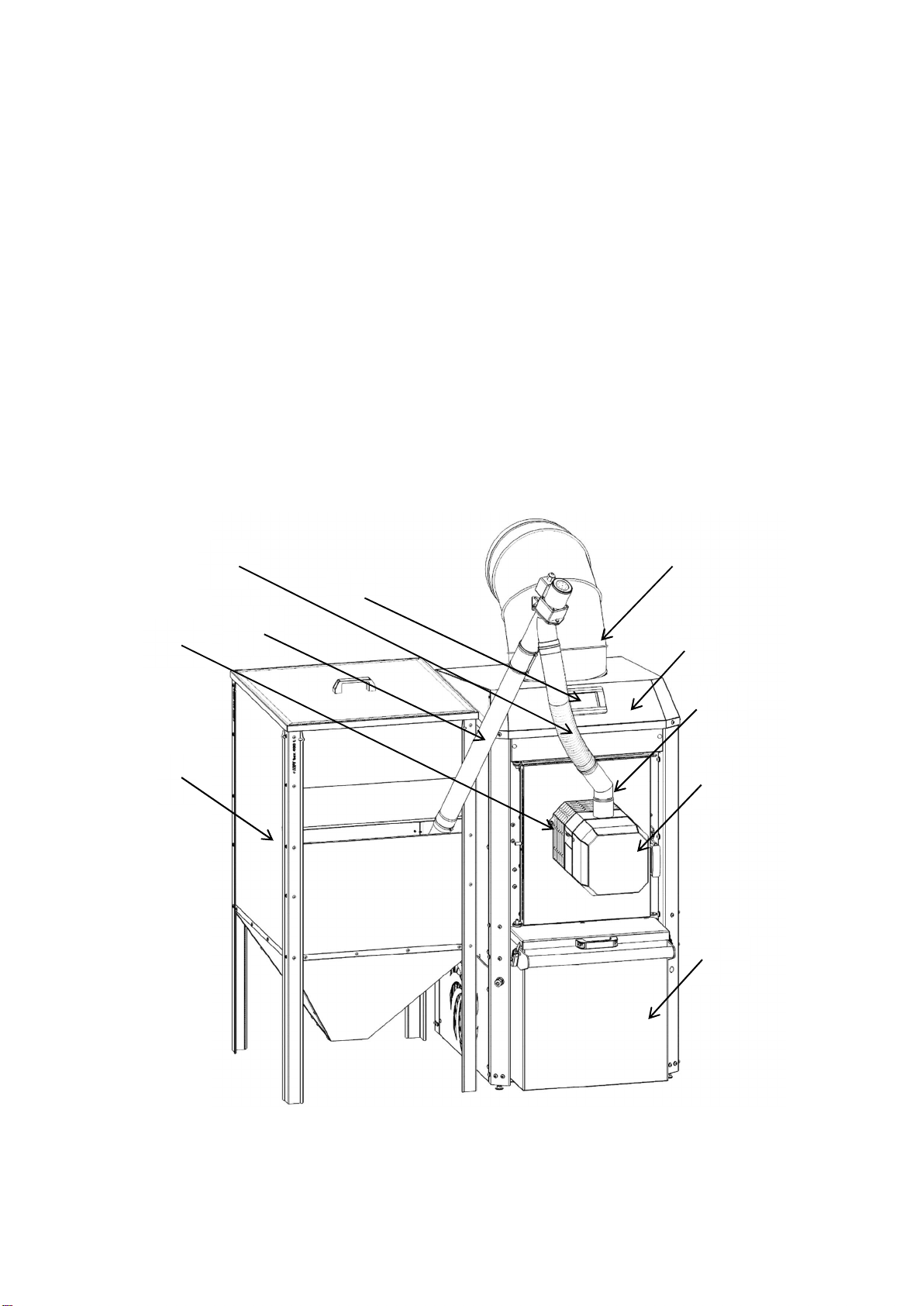
10
1. heater body, with a built-in exchanger, automatic ash removal mechanism, radial blower
fan, as well as removable elements such as:
1.1. air outlet duct,
1.2. removable ash pan
2. ROTARY KIPI burner, along with: zewnętrznym podajnikiem paliwa,
2.1. connection elbow,
2.2. 2.2. flexible spiro pipe,
2.3. 2.3. mounting flange,
2.4. 2.4. the 920 Touch regulator
cubature fuel container adjusted to the heater
Dig. 3. Components of the KIPI air heater kit.
1.1
1
1.2
2
2.1
2.4
2.5
3
2.2
2.3
Dieses Handbuch passt für folgende Modelle
7
Inhaltsverzeichnis
Beliebte Heizung Handbücher anderer Marken


Empire Heating Systems
Empire Heating Systems WCC65 Bedienungsanleitung

Wetekom
Wetekom 92 86 43 Bedienungsanleitung

Desa
Desa SPC170-F Bedienungsanleitung

Watlow
Watlow Watrod Electric Tubular Heaters Bedienungsanleitung

Haverland
Haverland ECO-DRY GPS Series Stücklistenhandbuch

Stelpro
Stelpro ASILVC2060 Series Bedienungsanleitung