
Labotek Desiccant Flex Dryer Bedienungsanleitung
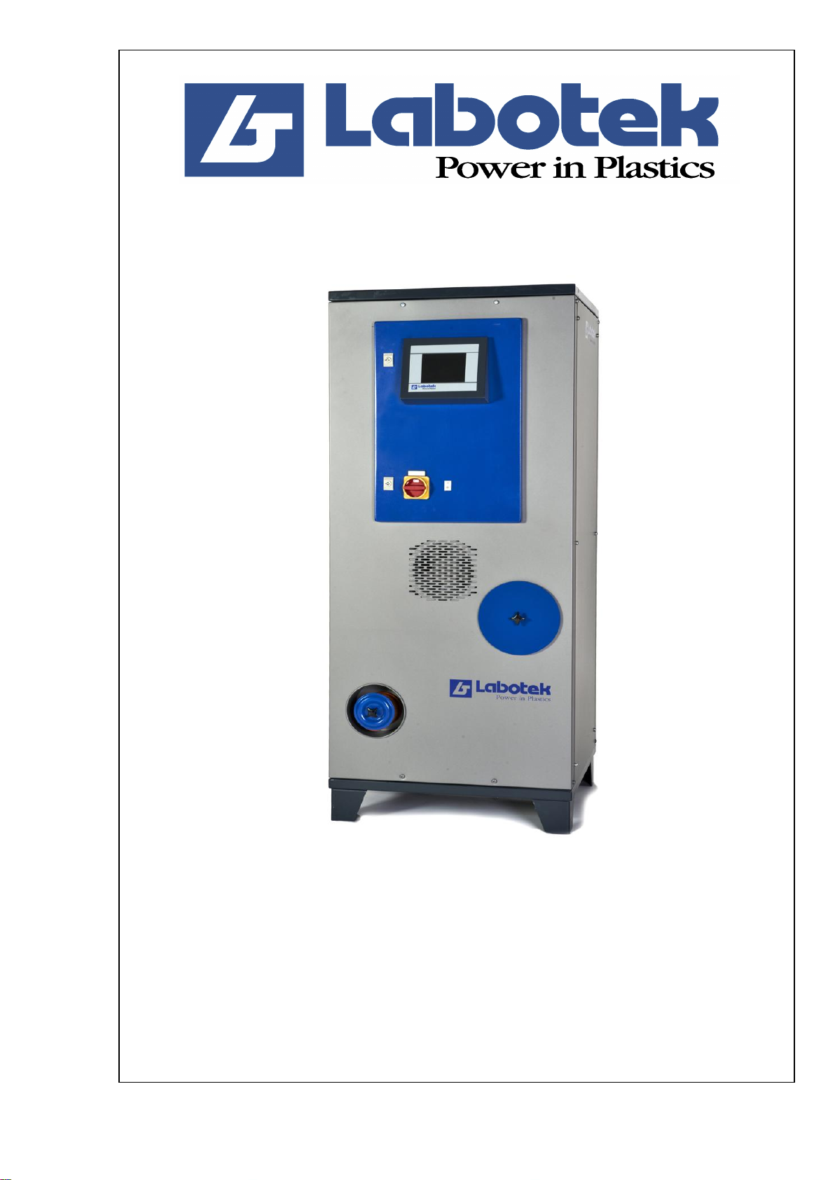
MANUAL
Desiccant Flex Dryer
DFD
Serial No....................
ISO 08.01.02.39.GB
LT nr.: 986408
Rev. 01
Maskine indeks:

Rev. 01 Desiccant Flex Dryer DFD Side 1 af 40
1.0 CONTENTS........................................................................................................... 1
2.0 GENERAL INFORMATION........................................................................... 2
2.1 Application............................................................................................................................ 2
2.2 Restrictions ........................................................................................................................... 2
2.3 Design................................................................................................................................... 3
2.4 Relevant directives................................................................................................................ 4
2.5 Operating principles.............................................................................................................. 4
2.6 Certificates............................................................................................................................ 6
3.0 TECHNICAL DATA......................................................................................... 8
3.1 Technical specifications........................................................................................................ 8
3.2 Typeplate .............................................................................................................................. 9
3.3 Dimensioned drawings ....................................................................................................... 10
3.4 Capacity table ..................................................................................................................... 11
3.5 Safety measures .................................................................................................................. 11
3.6 Noise level .......................................................................................................................... 12
4.0 INSTALLATION/OPERATION...................................................................12
4.1 Packing and transport.......................................................................................................... 12
4.2 Installation/connection........................................................................................................ 12
OPERATING THE SYSTEM..................................................................................14
5.1 Operating - LAB DRY........................................................................................................ 14
6.0 TROUBLESHOOTING .....................................................................................29
6.1 Machine gives en error message......................................................................................... 30
7.0 MAINTENANCE............................................................................................. 31
7.1 Maintaining the desiccant bed ............................................................................................ 31
7.2 Maintaining the air filters ................................................................................................... 31
7.3 Cleaning/checking the regeneration cooler......................................................................... 32
8.0 REPAIRS.......................................................................................................... 33
8.1 Replacing the desiccant bed assembly................................................................................ 33
8.2 Replacement of balls in the valve unit................................................................................ 36
8.3 Replacement of the motor for the change-over valve......................................................... 38
8.4 Replacement of blowers...................................................................................................... 39
8.5 Replaceing the fresh air valve............................................................................................. 40

Rev. 01 Desiccant Flex Dryer DFD Side 2 af 40
2.0 GENERAL INFORMATION
2.1 Application
The Desiccant Flex Dryer (DFD) is a central desiccant dryer designed for continuous drying of
granular plastic materials to a final moisture content of 0.02% or lower, depending on the material
involved. DFD is usually connected to a number of Drying Hoppers (DH hoppers).
See also separate manual on DH drying hoppers.
The DFD dryer has been designed for drying hygroscopic raw materials, nonhygroscopic raw
materials and regrinds in the temperature range from 60°C to 140°C with a temperature deviation of
±2°C or better.
2.2 Restrictions
The DFD unit may only be used for the purposes specified. It cannot be used for powders or liquids,
or for living creatures.
IMPORTANT!
The owner or the person responsible for connecting the apparatus and initiate operation shall make
sure that the installation is made in accordance with the requirements described in this manual.
Moreover, the owner or person must ensure that all safety procedures concerning the installation are
adequate and meet with local regulations.
The apparatus must be operated by a qualified operator only, following the procedures described in
this manual.
If the apparatus is operated by unauthorized or unqualified personnel resulting in damage to
property or personal injury, or is operated by or deposit with third party, all claim for compensation
covered by the product guarantee will become invalid and cancelled.
The right to carry out changes in the design is reserved to Labotek or his representative without
Labotek undertaking any obligation to change the design, neither for equipment already supplied.
The content of this manual is based on our present state of knowledge and is intended to provide
general information about the apparatus and its capabilities. The manual provides no further or
thorough description of the product characteristics or various fields of application.
The DFD unit may not be used in areas with danger of explosion.
Rev. 01 Desiccant Flex Dryer DFD Side 3 af 40
2.3 Design
2.3.1 DFD (Desiccant Flex Dryer)
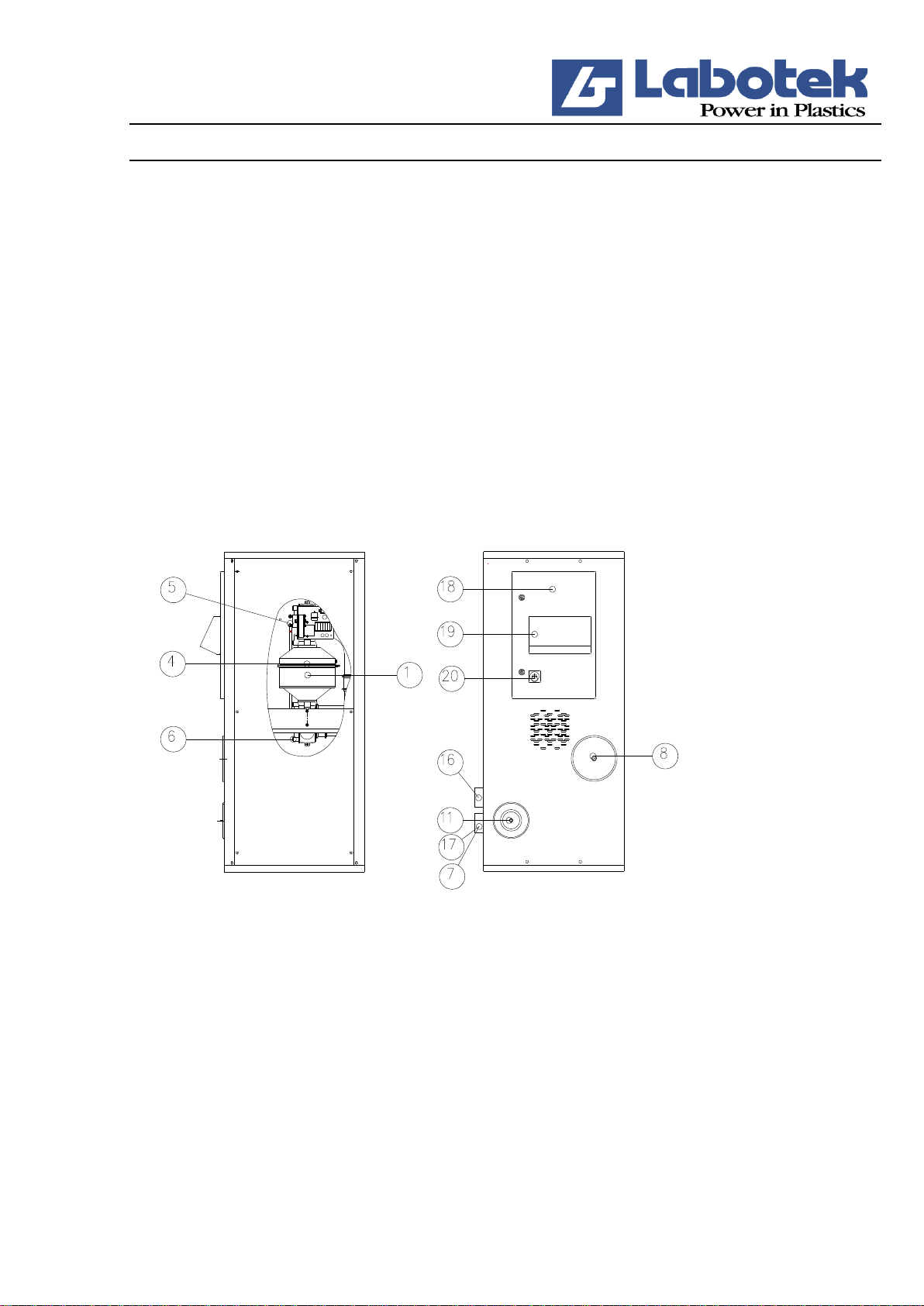
Pos. Item
(1) Desiccant bed assembly
(4) Heating elements for regeneration
(5) Valve unit for desiccant beds (upper)
(6) Valve unit for desiccant beds (lower)
(8) Return air cartridge filter
(11) Fresh air filter
(16) Return air pipe
(17) Return air pipe
(18) Control cabinet
(19) Microprocessor control (control panel)
(20) Power switch
R2647
The Desiccant Flex Dryer (DFD) operates in a closed system and is fitted with two desiccant beds
to dehumidify the air before use. One of the desiccant beds will always be operative in the drying
cycle while the other bed will be regenerating or in stand-by mode ready for activation into the
drying cycle.
The DFD dryer operates on the adsorption drying principle, i.e. the water molecules pass a water
adsorbent agent (the desiccant) which adsorbs the water molecules and releases them again during
regeneration. The desiccant used in the DFD dryer is called a molecular sieve.
It has a large surface to which the water molecules can affix. The water is removed from the
desiccant by heating (regeneration).

Rev. 01 Desiccant Flex Dryer DFD Side 4 af 40
The adsorption and regeneration processes take place without chemical transformation of the
desiccant which therefore has a long life. Deterioration of the desiccant is caused solely by soiling
of the surface of the desiccant with oil, dust etc. The desiccant in the DFD dryer is therefore
protected by an efficient dust filter which can easily be cleaned and replaced.
Easy operation
Only international function keys with simple standard symbols are used in the control panel.
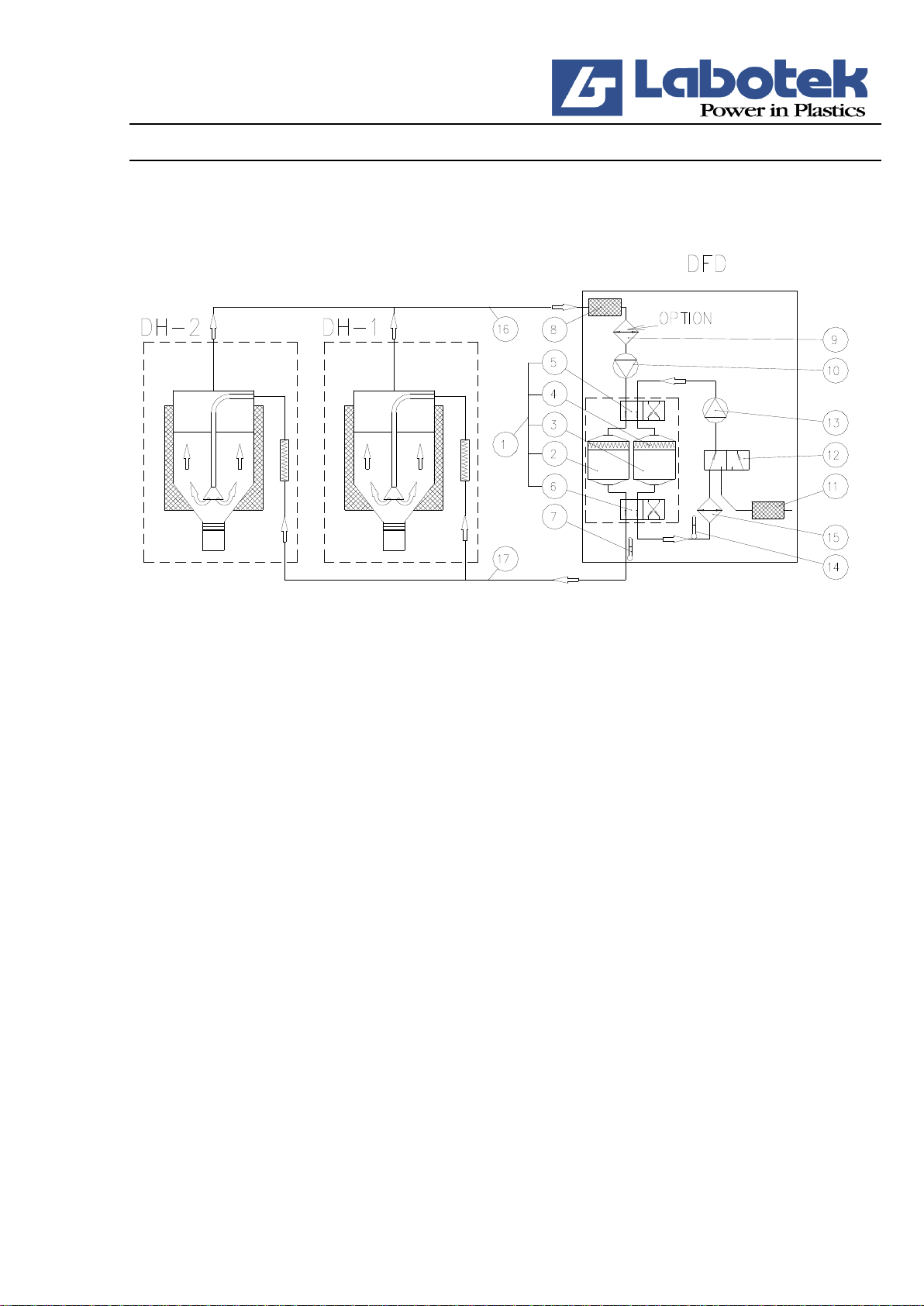
Desiccant bed assembly (l): Consists of two identical desiccant beds (2) and (3) with a built-in
heating element (4) for regeneration; the heating element is fastened between two valve units (5)
and (6).
Return air cartridge filter (8): Consists of one cartridge filter which is placed in a specially
designed box. The filter separates dust from the return air before it is recirculated through the
desiccant bed system.
Return air cooler (9) (optional): Reduces the drying air temperature before it is recirculated
through the desiccant bed to ensure optimal adsorption.
Desiccant air blower (10): Recirculates the drying air to the DH hoppers continuously.
Fresh air filter (11): Filters dust from the ambient air before it is used in the regeneration cycle.
Fresh air valve (12): A 3-way/2-way valve change-over between open and closed systems in the
regeneration phase.
Regeneration blower (13): Recirculates the regeneration air in the regeneration phase.
PT 100 sensor for regeneration air (14): Regulates the regeneration phases on the basis of
measurements of the regeneration temperature.
Regeneration air cooler (15): Is connected in the fi nal phase of the regeneration cycle to cool the
desiccant bed in a closed system.
Control cabinet (18): The control and electric and operating components are located inside the
cabinet or on the outside of the cabinet.
2.4 Relevant directives
We refer to accordance agreement attached.
2.5 Operating principles
2.5.1 Drying (Fig. R1862)
The drying air is circulated in a closed system by means of the desiccant air blower (10). The air is
dried in one of the two desiccant beds (2) or (3), and the dew-point temperature is lowered to below
-30°C.
Rev. 01 Desiccant Flex Dryer DFD Side 5 af 40
After the drying air has heated the raw material and transformed the moisture to water vapour, it is
fed back through the return air cartridge filter (8). The humid air may then be cooled by the return
air cooler (9) (optional) just before it reaches the blower (10).
R1862
2.5.2 Regeneration (Fig. R1862)
The DFD dryer has 2 desiccant beds (2) and (3) with molecular sieves for dehumidifying of the
drying air. One of the beds is always operative in the drying cycle whereas the other is either
regenerating in the regeneration cycle or, when fully regenerated, is in stand-by mode.
Regeneration occurs when hot air passes through the desiccant bed (2) or (3).
The regeneration blower (13) takes in ambient air through the fresh air filter (11) and the fresh air
valve (12) and sends it to the heating element for regeneration (4) where the air temperature is
increased to approx. 180°C. The moisture adsorbed in the desiccant bed is evaporated and is forced
into the ambient air in the form of water vapour.
In the last phase of the regeneration cycle, the heating element for regeneration (4) is disengaged
and as the position of the fresh air valve (12) changes, the air is recirculated in a closed system
where the air is cooled down through the regeneration air cooler (15).
The desiccant beds (2) and (3) are placed between 2 automatic, double-acting valve units (5) and (6)
ensuring that one of the desiccant beds is always operative in the drying cycle and the other in the
regeneration cycle. The desiccant beds switch every 90 to 180 minutes depending on the load on the
desiccant beds.
The time required for regeneration of a desiccant bed, depending on the amount of moisture
adsorbed, is controlled by the regeneration sensor (14) which is mounted on the discharge pipe of
the regeneration cycle.
Rev. 01 Desiccant Flex Dryer DFD Side 6 af 40
2.6 Certificates
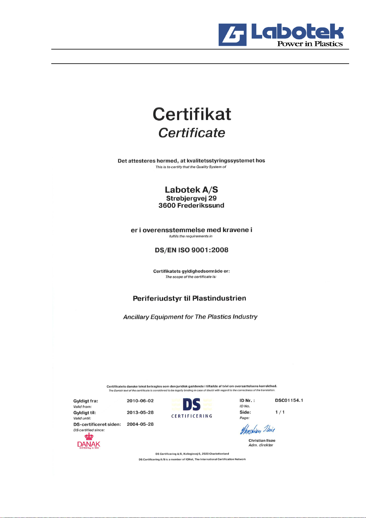
2.6.1 IQ-Net Certificate
Rev. 01 Desiccant Flex Dryer DFD Side 7 af 40
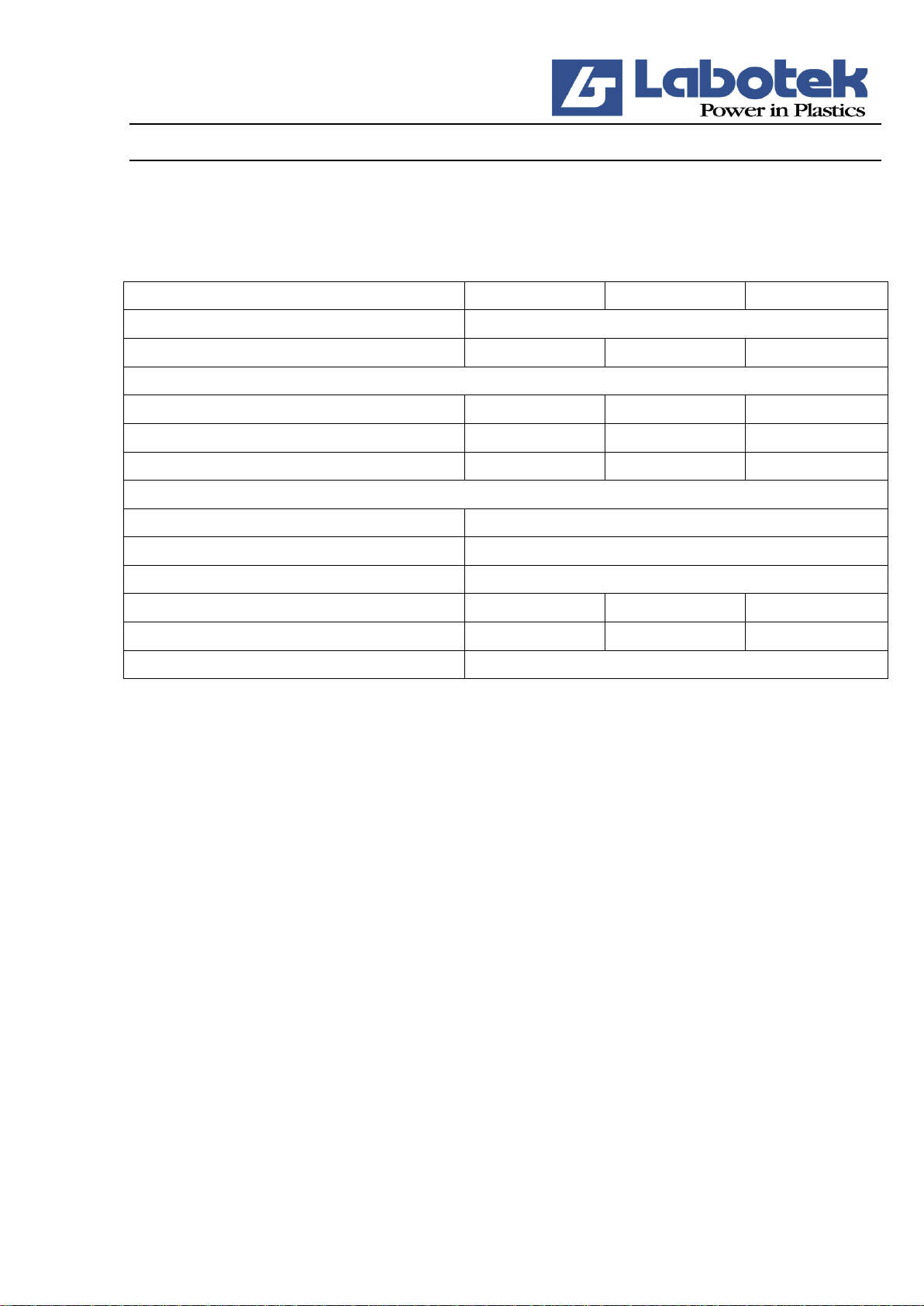
2.6.2 ISO- Certificate
Rev. 01 Desiccant Flex Dryer DFD Side 8 af 40
3.0 TECHNICAL DATA
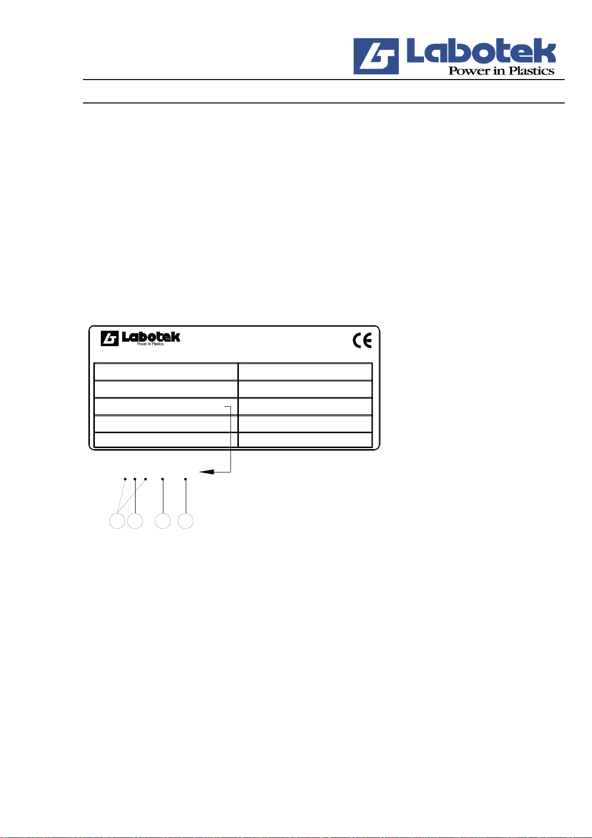
3.1 Technical specifications
Tekniske specifikationer
DFD 100
DFD 150
DFD 200
Supply voltage:
3 ~50/60 Hz , 380/415/440 V
Installed power excl. DH [kW]
5,5/5,8
5,5/5,8
7,3/7,7
Blower motor, drying:
3-phase 50/60 Hz [kW]
1,5/1,9
1,5/1,9
3,4/4
Air volume [m3/h] 50/60 Hz
100/120
150/180
200/240
Air Pressure [mm WS]
2400/2880
2400/2880
2400/2880
Blower motor, regeneration:
3-faset 50/60 Hz [kW]
0,37/0,44
Dew-point temp. [°C]
-30
Heating element regeneration [kW]
2x3,5/3,5
Power consumption [kWh]
2,0-2,6
3,5-4,5
5,5
Noise level [dBA]
65
65
65
Connecting cable [m]
3
We reserve the right to make changes to the specifi cations without notice.
Rev. 01 Desiccant Flex Dryer DFD Side 9 af 40
3.2 Typeplate
The identification number consists of a code (A) and (B), a type number (C) and a serial number
(D).
A) Identify the year in which the machine was manufactured. Example: 0SA8 = 2008
B) The first letter identifies the machine.
SA = Standard machine.
KA = Special customised design.
L = Low temperature (below 60°C)
H = High temperature (over 140°C)
The second letter states the machine index, in other words the current version.
Strøbjergvej 29
DK-3600 Frederikssund
Denmark
Tel: +45 48 21 84 11
Fax: +45 48 21 80 00
www.labotek.com
Type:
Model no:
Serial no:
Date: kW:
Hz:
Volt:
Prefuse:
Amp:
1KC1 10700501
CB D
50 Hz
7 kW
16 Amp
16 AMP
3x400+PE
2011.04
1KC1 10700501
101653
DFD200
A
Diagram:
R2648
C) The type number consists of two/three digits characterising the machine type:
DFD 100:
24
DFD 150:
16
DFD 200:
107
D) The serial number is a four/five-digit number referring to the individual manufacturing number
of the machine.
Dieses Handbuch passt für folgende Modelle
1
Inhaltsverzeichnis
Beliebte Trockner Handbücher anderer Marken


Indesit
Indesit IDV 75 Bedienungsanleitung

Infiniton
Infiniton SD-DG85C Bedienungsanleitung

BOMANN
BOMANN WT 5019 Bedienungsanleitung

Alliance Laundry Systems
Alliance Laundry Systems TMB795C Bedienungsanleitung

Asko
Asko T793C Bedienungsanleitung

Kenmore
Kenmore 8041 - 5.8 cu. Ft. Capacity Electric Dryer Bedienungsanleitung