Laing BM mini Series Bedienungsanleitung

Installation and operation manual
for mixing set BM mini

2
Installation and operation manual BM mini
www.laing.de
www.laing.de
www.laing.de
Design BM mini
1. Version KF = Remote sensor thermostat (8-26°C, 5 m) or
Version RT = thermoelectric drive for the connection of a room
thermostat (not included in delivery) or
Version KR = thermoelectric drive, pre-wired with pump including
a constant temperature control (A1-121 R, 20-70°C) for the
connection of a room thermostat (not included in delivery)
2. Laing circulating pump with spherical motor A1-121 resp. A1-121 R
3. Venting device
4. Supply radiator-/boiler circuit
5. Return radiator-/boiler circuit
6. Supplyoorheatingcircuit
7. Returnoorheatingcircuit
8. Adjustable mixing valve
9. Adjustable bypass for the radiator-/boiler circuit
(recommended to be closed)
10. ON-OFF-switch for pump
11. Flow temperature setting (KR version only)
10
2
6
7
9
5
4
8
1
3
11

www.laing.de
3
www.laing.de
Installation and operation manual BM mini
Table of contents
Design BM mini ...........................................................................................2
Technical Data..............................................................................................3
Application....................................................................................................4
Mounting instructions....................................................................................4
Hydraulic connection ....................................................................................5
Filling and priming the UFH system..............................................................6
Starting of operation without given values..................................................12
Starting of operation with given values (pre-setting) .................................. 13
Assembly of wall bracket............................................................................15
Dimensional drawing ..................................................................................16
Pump curve ................................................................................................16
Product range, accessories and spare parts..............................................17
Electrical connection...................................................................................18
Technical Data
Max. system pressure 1 Mpa (10 bar)
Max.systemtemperature 110°C(boilercircuit),55°C(oorheating)
Max. differential pressure 100 kPa (1 bar) in the
radiator-/boiler circuit
Electrical connection 1 x 230 V / 50 Hz
Power consumption 25 Watt (circulating pump)

4
Installation and operation manual BM mini
www.laing.de
www.laing.de
www.laing.de
Application
• TheBMminiisdesignedtosupplyoorheatingareasuptoapprox.40
sqm (from pipe 16x2 mm onwards) in one- or two-pipe-systems. The
connectionofupto2oorheatingcircuitsispossible.
• Three versions are available:
BM mini KF: Mixing set with room temperature guided control,
made of thermostat (10-26°C + frost protection)
with remote sensor (5 m).
BM mini RT: Mixing set for temperature guided control, made
of thermoelectric drive for the connection of a room
thermostat (room thermostat not included in
delivery- see accessories in product range).
BM mini KR: Mixing set with integrated constant temperature
control (20-70°C) for the connection of a room
thermostat (room thermostat not included in
delivery- see accessories in product range).
• The BM mini is provided with a temperature protection system that
restrictsthesupplytemperatureintheoorheatingcircuittomax.55°C.
Mounting instructions
• BM mini will be connected directly to the existing radiator-/boiler circuit.
• When two circuits are connected to the BM mini, the shortest circuit
must be balanced by using an adjustable return screw connection.
• The BM mini has to be mounted in a horizontal position (see page 2).
Left or right connection to the radiator-/boiler circuit is possible (see
page 9).
• TheBMminihastobeinstalledonahigherlevelthantheoorheating
installation.

www.laing.de
5
www.laing.de
Installation and operation manual BM mini
• Ensure that the pre-pressure to the BM mini from the radiator-/vessel
circuit is minimum 10 kPa (1 m).
• BeforerunningtheBMminipleasecheck,thattheoorheatingsystem
islled,completelyvented,andprovedagainstleakage.
• Since the circulation pump might create under certain circumstances
someownoise,theBMminishouldbeplacedawayfromnoise
sensitive areas (i.e. sleeping rooms).
• The water temperature in the supply radiator-/boiler circuit should be at
least10Khigherthanintheoorheatingsupply.
• The maximum length of each pipe must not be longer than 100 m for
oorheatingdesignwithspreadof10Kwhenusingpipes12mmi.d.
(i.e. pipe 16x2). Smaller diameter pipe results in a shorter pipe length.
• BM mini KF: Assemble the thermostatic head and mount the
sensor in an appropriate position in the room and
about1,7mabovetheoor.Useavacantpipeif
possible.
• BM mini RT: Wiring of the electrical actuator and the room
thermostat
BM mini KR: onlybyaqualiedelectrician.
Hydraulic connection of two-pipe systems
Bypass valve closed.
Allen key 2,5mm.

6
Installation and operation manual BM mini
www.laing.de
www.laing.de
www.laing.de
Filling of the system
Itismandatorytoushtheoorheatingloopsbeforeputtingthesystem
in operation, because otherwise malfunction or damage to the pump may
result.WerecommendusingtwollvalvesontheprimarysideoftheBM
miniasshowninpicture2.Alternatively,thesystemcanbelledusingll
valves installed elsewhere in the system. In any case, it is necessary to
positivelyushthesystemsinceotherwisetheairinthesystemwillnotbe
purged completely. Filling the system via the integrated manual air vent
(see picture 7) is not possible! Please observe the position of the ball valve
inthebypass.Ifthisisintheverticalposition,theoorheatingloopsare
hydraulically uncoupled from the boiler loop. This position is ideal for nor-
mal operation (see picture 1) since the pump in the heating loop does not
inuencetheoorheatingloop.Withthevalveinthisposition,however,the
oorheatingsystemcannotbelledfromtheprimaryside.
Tolltheoorheatingloopsfromtheheatingloopside,thisballvalvemust
beclosed(horizontal)–seepictures2through6.Afterlling,thevalve
mustbeopenedagain(verticalposition).Pleaseobservethatwhenlling
from the primary side radiator valves on that side should be closed in order
tohavemaximumpumppressureavailableforpurgingtheoorheating
loops.

www.laing.de
7
www.laing.de
Installation and operation manual BM mini
! ! !
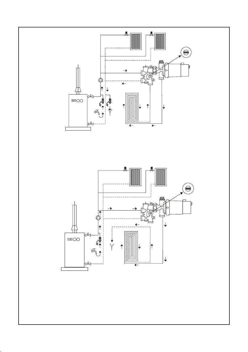
Normal operation. Ball valve position open (vertical)
!!!
Recommendedllingofthesystem.Twollvalvesontheprimarysideofthe
BMminiallowforaneasyllingandpurgingofairintheoorheatingloops.
The ball valve position must be closed (horizontal).
Picture 1
Picture 2
8
Installation and operation manual BM mini
www.laing.de
www.laing.de
www.laing.de
! ! !
Goodllingoption.Twoexistingllvalvesontheprimarysideallowforgood
llingandairpurging.Theballvalvepositionmustbeclosed(horizontal).
! ! !
Possiblellingoption,albeitalittlecomplicated.Onellvalveontheprimary
owsideallowsforllingandairpurging.Theintegratedballvalvemustbe
closed (horizontal). Caution:TheoorheatingreturnattheBMminimustbe
closedduringthelloperation.Fillingawallheatingloopisimpossibleinthis
way.
Picture 3
Picture 4

www.laing.de
9
www.laing.de
Installation and operation manual BM mini
!!!
Possiblellingoption,albeitalittlecomplicated.Onellvalveontheprimary
returnsideallowsforllingandairpurging.Theintegratedballvalvemustbe
closed (horizontal). Caution:TheoorheatingowattheBMminimustbe
closedduringthelloperation.Fillingawallheatingloopisimpossibleinthis
way.
Picture 5

10
Installation and operation manual BM mini
www.laing.de
www.laing.de
www.laing.de
!!!
Thedirectionofowshownisonlypossibleifthereisnocheckvalve
installed at the primary heating circulator. If a check valve is present,
llinginaccordancewithpicture3isrecommended.
Picture 6
Dieses Handbuch passt für folgende Modelle
3
Inhaltsverzeichnis
Beliebte Steuereinheit Handbücher anderer Marken

Festo
Festo Compact Performance CP-FB6-E Stücklistenhandbuch

Elo TouchSystems
Elo TouchSystems DMS-SA19P-EXTME Bedienungsanleitung

JS Automation
JS Automation MPC3034A Bedienungsanleitung

JAUDT
JAUDT SW GII 6406 Series Kurzanleitung

Spektrum
Spektrum Air Module System Bedienungsanleitung

BOC Edwards
BOC Edwards Q Series Bedienungsanleitung


