Lake Shore Cryotronics 372 Bedienungsanleitung

1 http://www.lakeshore.com/products/ac-resistance-bridges/model-372/ Model 372 Quick Start Guide
Quick Start Guide
Model 372 AC Resistance Bridge and Temperature Controller

2Model 372 Quick Start Guide
Safety Precautions
Observe these general safety precautions during all phases
of instrument operation, service, and repair. Failure to comply
with these precautions or with specific warnings elsewhere in
this manual violates safety standards of design, manufacture,
and intended instrument use. Lake Shore Cryotronics, Inc.
assumes no liability for Customer failure to comply with these
requirements.
The Model 372 protects the operator and surrounding area
from electric shock or burn, mechanical hazards, excessive
temperature, and spread of fire from the instrument.
Environmental conditions outside of the conditions below may
pose a hazard to the operator and surrounding area.
Indoor use
Altitude to 2000 m
Temperature for safe operation: 5 °C to 40 °C
Maximum relative humidity: 80% for temperature up to
31 °C decreasing linearly to 50% at 40 °C
Power supply voltage fluctuations not to exceed ±10% of
the nominal voltage
Overvoltage category II
Pollution degree 2
Ground the Instrument
To minimize shock hazard, the instrument is equipped with
a 3-conductor AC power cable. Plug the power cable into an
approved 3-contact electrical outlet or use a 3-contact adapter
with the grounding wire (green) firmly connected to an electrical
ground (safety ground) at the power outlet. The power jack and
mating plug of the power cable meet Underwriters Laboratories
(UL) and International Electrotechnical Commission (IEC) safety
standards.
Ventilation
The instrument has ventilation holes in its top and side covers. Do
not block these holes when the instrument is operating.
Do Not Operate in an Explosive Atmosphere
Do not operate the instrument in the presence of flammable
gases or fumes. Operation of any electrical instrument in such an
environment constitutes a definite safety hazard.
Keep Away from Live Circuits
Operating personnel must not remove instrument covers. Refer
component replacement and internal adjustments to qualified
maintenance personnel. Do not replace components with power
cable connected. To avoid injuries, always disconnect power and
discharge circuits before touching them.
Do Not Substitute Parts or Modify Instrument
Do not install substitute parts or perform any unauthorized
modification to the instrument. Return the instrument to an
authorized Lake Shore Cryotronics, Inc. representative for service
and repair to ensure that safety features are maintained.
Cleaning
Do not submerge instrument. Clean only with a damp cloth and
mild detergent. Exterior only.
Desktop Installation
When installing the instrument in a desktop environment, ensure it
is mounted on a flat, level surface.

3 http://www.lakeshore.com/products/ac-resistance-bridges/model-372/ Model 372 Quick Start Guide
Improper Use
If the instrument is used in a manner that is not specified by Lake
Shore, the safety protections provided by the instrument are no
longer guaranteed, and may be impaired.
Introduction
Congratulations on purchasing the world’s most
advanced ultra-low temperature controller.
This guide provides basic information for getting
started with your AC resistance bridge and temperature
controller. For further documentation and information,
please see http://www.lakeshore.com/products/ac-
resistance-bridges/model-372/pages/Downloads.aspx.
Items included with the Model 372 AC resistance bridge
and temperature controller:
Model 372 instrument
Model 372 user’s manual
Line power cord
3 sensor input mating connectors, 6-pin DIN
Terminal block mating connector, 6-pin terminal block, for
relays 1 and 2
Terminal block mating connector, 7-pin terminal block, for
heater and analog outputs
Unpacking
1. Inspect shipping containers for external damage
before opening them.
2. Photograph any container that has significant
damage before opening it.
3. Inspect all items for both visible and hidden damage
that occurred during shipment. If there is visible
damage to the contents, contact the shipping
company and Lake Shore immediately
NOTE: Procedures vary slightly with shipping
companies. Keep all damaged shipping materials
and contents until instructed to either return or
discard them.
4. Open the shipping container and keep the container
and shipping materials until all contents have been
accounted for.
5. Check off each item on the packing list as it is
unpacked.
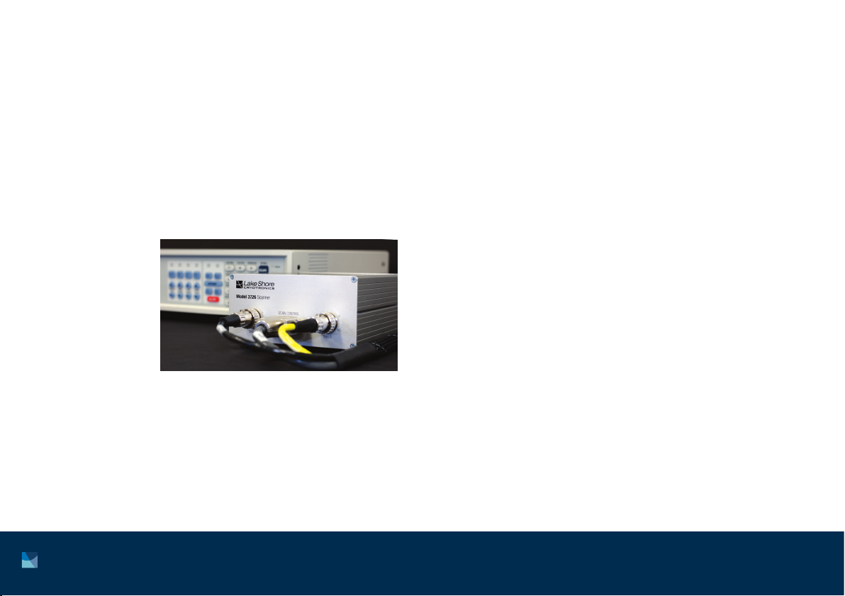
Optional. If you ordered a Model 3726 or Model 3708
scanner, it may be shipped separately.

4Model 372 Quick Start Guide
Keypad operation
See Chapter 4 of the Model 372 user’s manual for
detailed descriptions of each key.
Front panel Rear panel
The rear panel consists of:
1. Scanner control connector
2. Measurement input connectors
3. Control input connector
4. Diagnostic monitor output connector
5. Reference output connector
6. Sample heater, warm-up heater and analog output
terminal block connector
7. Relays 1 and 2 terminal block connector
8. RJ-45 Ethernet interface
9. USB type-B port
10. IEEE-488 interface
11. Line input assembly
3
1
2
4 5 6 7 8 9 10
11
5 http://www.lakeshore.com/products/ac-resistance-bridges/model-372/ Model 372 Quick Start Guide
Placement
The Model 372 is an out-of-the-box benchtop instrument
with adjustable legs to tilt the instrument up slightly for
an improved viewing angle.
It is also possible to mount the Model 372 in an
instrumentation rack. This requires an RM-1 rack-mount
kit that can be purchased separately from Lake Shore if
required.
Startup
The steps that follow will take you through to displaying
measurements from a single temperature sensor.
This is just the beginning of what is possible with the
Model 372, but is a good introduction to the unit.

6Model 372 Quick Start Guide
Basic temperature operation
1. Make the following connections to the Model 372:
a. Power connection using the supplied power cord. Do not switch the unit on until all other connections are
made.
b. Sensor connection to the measurement input. This can be a complex step; if this is the first time you have
wired a sensor to either a Model 370 or 372, please see section 3.5 of the Model 372 user’s manual.
This process will be different depending on whether a scanner is also to be used with the instrument. For
guidance on using this additional device, please see section 3.6 of the Model 372 user’s manual. The rest of
these steps assume that the sensor is connected directly to the Model 372, though notes will be made when
something will be different in the case of having a scanner connected.
V+
V– I+ I–
sensor

7 http://www.lakeshore.com/products/ac-resistance-bridges/model-372/ Model 372 Quick Start Guide
c. Communications connection to your PC using one of the three different methods available (USB, Ethernet,
GPIB). For this example, USB is used as the connection method.
2. Turn on the Model 372 using the power switch on the back of the instrument. The default settings will display a
resistance reading for the sensor that you have connected. Even if the sensor is at room temperature, you should
see a logical resistance reading. If not, check your connections and begin troubleshooting until a logical reading
is displayed. In the example below, a 10.009 kWsensor reading is shown.

8Model 372 Quick Start Guide
3. To convert this resistance measurement to Kelvin, run the Curve Handler program found at
www.lakeshore.com/products/pages/curvehandler.aspx. Curve Handler can also be found on the Model 372’s
web server that can be accessed when connecting to the instrument via Ethernet (see section 6.4 of the Model
372 user’s manual for details on making this connection). The USB connection will show up as a virtual COM port
on your PC. Select the appropriate COM port from the drop-down menu and click Connect.

9 http://www.lakeshore.com/products/ac-resistance-bridges/model-372/ Model 372 Quick Start Guide
4. If you are not able to connect, make sure you have the correct COM port selected. You can do this by checking
Device Manager:
If you are unable to see the Model 372 in this view, you may need to install the USB driver that can be found on
the Lake Shore Software web page.

10 Model 372 Quick Start Guide
5. Load the sensor calibration file that matches the connected sensor by clicking the Open button and navigating
to the appropriate file.
These calibration files can be
found on the USB drive that
was sent with the sensor, or
downloaded from
http://calibration.lakeshore.com.
The Model 372 supports both .340
and .curve file formats, with .curve
being the more modern format.
Inhaltsverzeichnis
Andere Lake Shore Cryotronics Temperaturregler Handbücher

Beliebte Temperaturregler Handbücher anderer Marken

Swegon
Swegon LUNAd MB Bedienungsanleitung

Lucky Reptile
Lucky Reptile Thermo Control II Bedienungsanleitung

SENSORMETRIX
SENSORMETRIX Argon 100 Bedienungsanleitung

Fuji Electric
Fuji Electric PXE4 Bedienungsanleitung

Yuyao gongyi
Yuyao gongyi XMT-808 series Bedienungsanleitung

Selec
Selec TC544C Bedienungsanleitung


