Linkam Scientific Instruments CI 94 Bedienungsanleitung

Page 1 CI 94 Manual
Linkam Scientific
Instruments Ltd
CI 94 Manual
User’s Guide

CI94 Manual Page 2
Contents
Regulatory Compliance ...................................................................................................... 3
Important Notice ............................................................................................................... 4
Warranty .......................................................................................................................... 4
Technical Support .............................................................................................................. 4
Equipment Maintenance .................................................................................................... 4
CI94 Technical Specification ............................................................................................... 5
CI94 Equipment Ratings .................................................................................................... 5
Safety Precautions ............................................................................................................ 6
Symbol Reference ....................................................................................................... 6
Introduction ...................................................................................................................... 7
Various Cables and Connections ......................................................................................... 8
Stage Lead ................................................................................................................. 8
RS232 Lead ................................................................................................................ 8
I2C Cable ................................................................................................................... 8
Back Panel Programmer Connections .................................................................................. 9
Front Panel Controller Buttons ......................................................................................... 10
Setup Menus Explained ................................................................................................... 11
Working with the Setup Menus ........................................................................................ 12
Linksys Temperature Control Software ............................................................................. 17
Getting Started ......................................................................................................... 17
Setting up a Temperature Profile ................................................................................ 17

Page 3 CI 94 Manual
Regulatory Compliance

CI94 Manual Page 4
Important Notice
Please check that your Linkam equipment has not been damaged during transport. If there is any
evidence of external damage DO NOT SWITCH ON ANY ELECTRICAL ITEMS.
Contact LINKAM SCIENTIFIC or their appointed distributor immediately. Your warranty maybe
impaired if Linkam is not informed of any transport damage within 7 days of delivery.
NO attempt should be made to repair or modify the equipment in any way, as there are no user
replaceable parts.
No attempt should be made to open the case except by qualified personnel as hazardous voltages are
present.
Please contact Linkam for custom modifications for specific applications.
In order to use this equipment successfully, please take time to read this manual all the way through
before starting to work.
Warranty
This equipment has a warranty against defects in material and workmanship for a period of 12
months. Linkam will either repair or replace products that prove to be defective. For warranty
service or repair, this product must be returned to Linkam or a designated service facility.
The warranty shall not apply to defects resulting from interfacing, unauthorized modification or
misuse, operation outside of the environmental specifications for the product, or improper site
preparation or maintenance.
Technical Support
Any technical questions or queries should be addressed to the Technical Support Department at the
address shown on the back of this manual.
Equipment Maintenance
The programmer does not require any regular maintenance. If for any reason it is necessary to
check the electronic calibration then a set of standard resistances can be supplied, which simply plug
into the programmer in place of the stage, and indicate known temperature values. The standards
are traceable to NAMAS.
Before cleaning the case or front panel of the programmer, remove the mains lead from the wall
outlet. Use a small quantity of isopropyl alcohol on a soft cloth and gently wipe the surface.

Page 5 CI 94 Manual
CI94 Technical Specification
Stages using a platinum resistor sensor
Temperature Range: -196°C to 600.0°C (dependent on Stage)
Temperature Stability: +/-0.1°C over the operating temperature of 10° to 40°C
Set Point Resolution: 1°C
Temperature Display: 0.1°C resolution
Control Stability: All stages stable to +/-0.1°C
Temperature Sensor: Pt100 1/10 DIN or 0.01 Ohm at 0°C
Temperature Accuracy: +/-0.1°C
Display: 1 row of 16 characters, 5.5mm high LCD display with backlight
Dimensions 310 x 230 x 80 (deep) mm
Weight: 2.44 Kg (including remote control and stage cable )
Operating environment: 5 ~ 40°C
80% relative humidity at 31°C decreasing linearly to 50% at 40°C (without
condensation)
CI94 Equipment Ratings
A.C.Mains Supply: 90 - 264 ~
A.C.Frequency: 47 - 63 Hz
Max current: 2A
Fuse: 2.5A (F) 250V~ Fuse must be replaced by one of the same type and rating.

CI94 Manual Page 6
Safety Precautions
1) Read all of this guide before using the equipment. Save these instructions for later use.
2) Follow all warnings and instructions which may be placed on the programmer or stage.
3) If for any reason the mains fuse needs to be replaced then it must be replaced by one of the same
type and rating as shown in the equipment ratings.
4) To prevent electric shock, do not remove the cover of the controller or associated electronics.
5) Never use the equipment if a power cable has been damaged. Do not allow any heavy objects
to rest on the power cables. Never lay the power cables on the floor.
6) Do not obstruct any ventilation holes. Do not attempt to insert anything into these openings.
Provide adequate ventilation of at least 75mm all around the equipment.
7) Do not expose the equipment to water. If for any reason it gets wet then unplug it from the mains
and contact Linkam Scientific Technical Support.
The equipment is not intended to be used outdoors.
8) Each product is equipped with a 3-wire grounded (earth) mains plug or a free-end 3 wire mains
lead. The plug only fits into a grounded-type outlet. The free-end mains lead should be connected
to a correctly grounded 3-wire mains outlet. Do not defeat the purpose of the grounded (earth)
type plug.
Free - end mains leads are colour coded as follows :
Colour Function
Brown Live
Blue Neutral
Green/Yellow Earth (Ground)
9) If any problems occur then unplug the all the equipment from the mains outlet and contact Linkam
Scientific Technical Support.
10) Do not remove the cover from the equipment unless the mains inlet has been removed.
Any servicing should be carried out by qualified service personnel.
Symbol Reference
Caution -
This safety symbol is seen on the backpanel of the equipment and warns:-
The user must not make or remove any connections while the unit is powered on.
To avoid electric shock do not remove the cover. Refer servicing to qualified service
personnel.
Caution -
This warning symbol indicates that the surface labelled with this symbol may be hot.

Page 7 CI 94 Manual
Introduction
The CI94 (Computer Interface) has been specifically designed to give precise temperature control of the
Linkam range of heating/freezing Stages. Digital linearisation of the Stage’s sensor gives accurate tem-
perature values whilst the function keys have been carefully chosen to allow rapid changes in data values.
A varying d.c. signal is used to control the Stage and results in an even application of power which avoids
the bursts seen with conventional burst fire a.c. techniques. Much finer control of the Stage temperature
can be now be achieved over the whole range.
Automatic control of the LNP 94/2 is possible which reduces the amount of liquid nitrogen used and gives
more repeatable results as the flow is continuously changed according to the set conditions.
The rate, limit and temperature can be superimposed onto a Video Camera Signal using a Linkam VTO232
Video Interface from the output provided.
The Linksys temperature control software enables extremely accurate and complex temperature profiles to
to be carried out and can be linked with the Linkam Real Time Video Measurement software so that
temperature control information can be in laid upon digitally captured images.

CI94 Manual Page 8
Various Cables and Connections
Stage Lead
This’D’type end of the cable plugs into the socket on the back of
the CI94 marked, ‘Stage Lead’.
Screw in the connector so that it does not dislodge accidentally
during a profile. The stage lead is specific to the stage, it carries
information in the connector that tells the programmer which stage
is connected. IN SPITE OF APPEARANCE NOT ALL STAGE
LEADS ARE THE SAME.
This end of the stage lead is called a lemo connector and plugs
directly into the stage.
RS232 Lead
This cable is the communication cable between the PC and the
CI94 when using the Linksys temperature control software, or
downloading CI94 software update.
Both ends are similar. One end plugs into the socket marked
‘RS232’ on the back of the CI94 and the other end plugs into either
COMM1 or COMM2 serial ports on the back of your PC
I2C Cable
This cable is the communication cable between the CI94 and the
LNP94/2 Automatic Cooling pump (or VTO232). Both ends are 4
pin connectors and plug into the sockets marked I2C on the back of
the CI94 and LNP94/2.
(It does not matter which I2C socket this cable is plugged into,
there is no ‘IN’ or ‘OUT’ socket i.e the two sockets next to each
other on the LNP94/2)

Page 9 CI 94 Manual
Stage lead
Expansion port (Not Used with CI94)
I/O port for remote control
RS232 communication cable to PC
Power cable
Mode Switch for Rateloading upgrades
I
2C communication between programmer and other electronic
Linkam products e.g LNP, VTO
On/Off Power Switch
Back Panel Programmer Connections
CI94 Manual Page 10
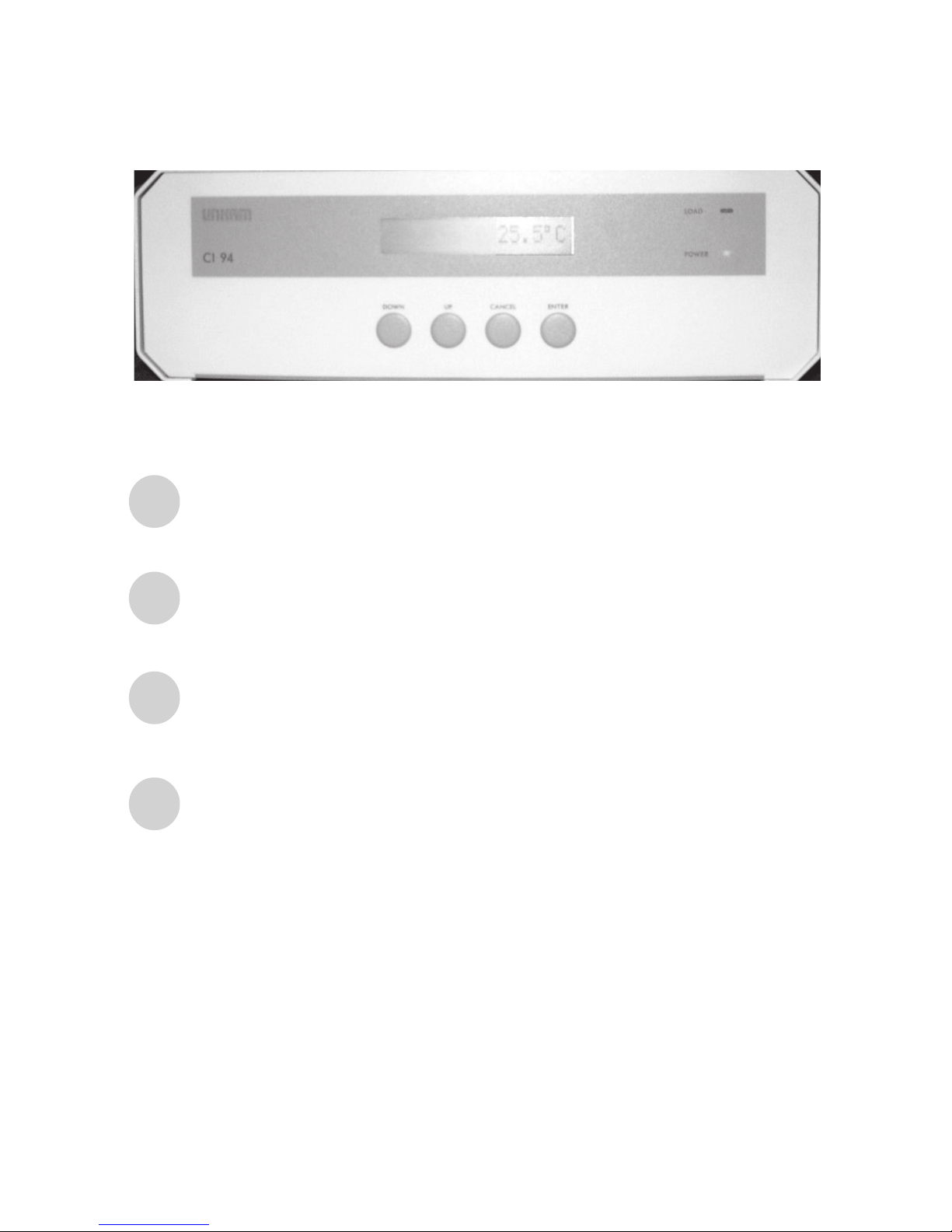
Front Panel Controller Buttons
DOWN
UP
ENTER
CANCEL
Move down a menu screen
Move up a menu screen
Cancels current menu screen and drops down to previous set of menus
Selects menu option or moves up to next set of menus.
Also exits a profile if software control is lost due to crash or RS232 cable loosing
its connection.
Inhaltsverzeichnis
Andere Linkam Scientific Instruments Temperaturregler Handbücher


Beliebte Temperaturregler Handbücher anderer Marken

Swegon
Swegon LUNAd MB Bedienungsanleitung

Lucky Reptile
Lucky Reptile Thermo Control II Bedienungsanleitung

SENSORMETRIX
SENSORMETRIX Argon 100 Bedienungsanleitung

Fuji Electric
Fuji Electric PXE4 Bedienungsanleitung

Yuyao gongyi
Yuyao gongyi XMT-808 series Bedienungsanleitung

Selec
Selec TC544C Bedienungsanleitung


