Loadsensing LS-G6 Piconode Bedienungsanleitung
Loadsensing LS-G6 Piconode
Configuring and operating the Loadsensing LS-G6 Piconode

Piconode
Piconode overview 2
Equipment 2
Piconode installation 2
Supports 2
Powering the Piconode 3
Piconode configuration 5
Step 1: Connect DLog Android application 5
Step 2: DLog main menu 6
Step 3: Sensor wiring and set up 7
Channel 1 for Full Wheatstone Bridge, Potentiometer/Ratiometric and Volt Single Ended 8
Channel 2- Thermistor 10
Channel 3 Pulse counter 11
Step 4: Sensors data 12
Step 5: Radio Network configuration 12
Radio Type 12
Radio off 12
LS Radio 14
Step 6: Radio Signal Coverage Test 17
Step 7: Test results interpretation 19
Safely closing the Piconode 22
Maintenance 22
Piconode Firmware Upgrade Procedure 22
Battery lifespan 23
Data Acquisition and storage 24
Pulse counter particularities - Engineering Units 24
Steps to reset the node configuration via Dlog app 24
Steps to reset the node configuration via Gateway configuration 25
1

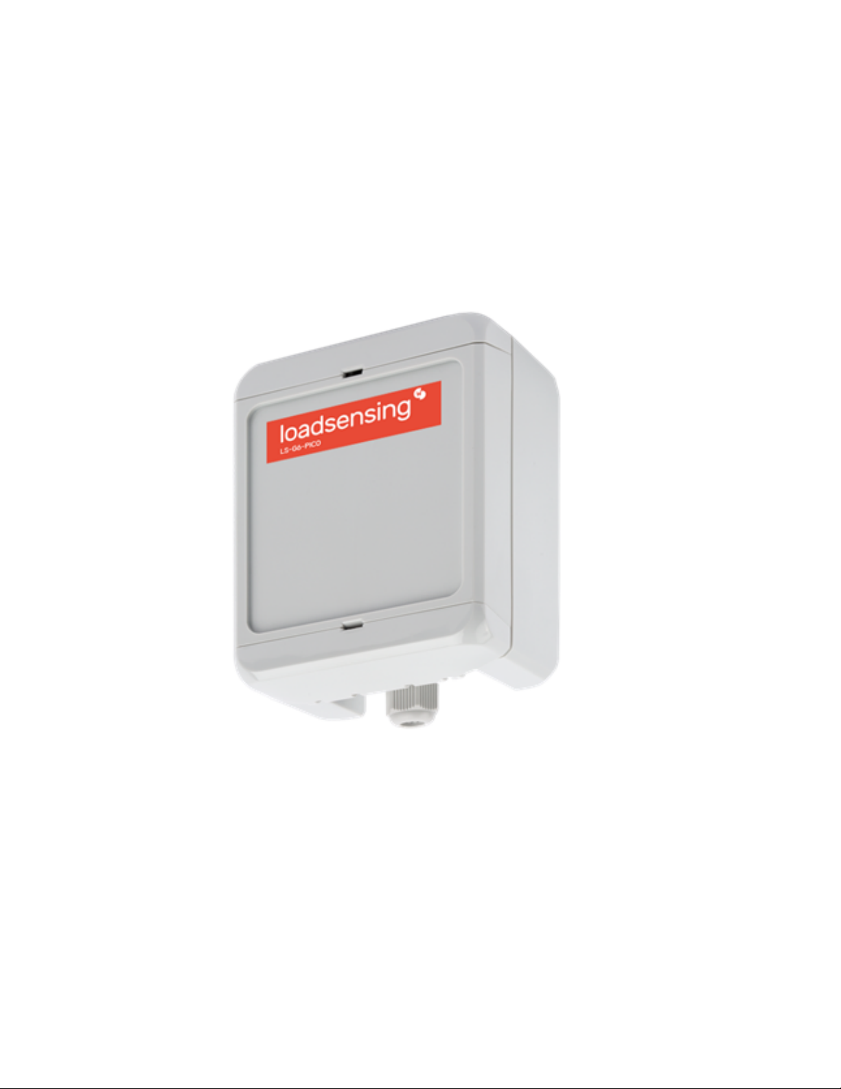
Piconode overview
The Worldsensing LS-G6-Piconode comprises a configurable single channel, a thermistor, and a pulse counter node.
It can be regarded as a simpler version of LS-G6-VOLT node, in the sense that it is compatible with sensors of
different analog signal output, such as full Wheatstone bridge, potentiometer/ratiometric, single-ended voltage
and thermistors, but with the novelty of being able to read potential-free (dry contact) pulses. The sensor’s voltage
excitation required to be compatible with the piconode is 5 VDV up to 70 mA. A distinctive feature of Piconode as
compared to LS-G6-VOLT and LS-G6 vibrating wire nodes is that it collects and transmits the internal temperature
at each reading, to an accuracy of 2 °C.
Unlike other LS-G6 nodes, the antenna in a piconode is located internally in the casing upper cover. The coverage
tests results prove that distances over five kilometres can be achieved in urban areas.
You can check the specifications of the piconode here: https://www.worldsensing.com/product/loadsensing/
Equipment
The Worldsensing LS-G6-Piconode is equipped with an internal antenna.
Other additional accessories can be supplied upon request. Here is a partial list, please inquire for other
accessories:
●USB-OTG configuration cable
●Batteries
●Sensor surge protection
●Mounting supports
Piconode installation
Supports
The Piconode can be mounted:
●On a wall - polycarbonate wall mounting brackets are available as additional accessories (refer to Figures 1, 2,
and 3)
2

●On a raised horizontal surface - same mounting brackets as above
●Inside a manhole (with a plastic or metallic cover) - no special accessories are available for this mounting type.
See Annex 10 LS-G6 Dataloggers installation on manholes for further detail
Figure 1: Plan and section views of the mounting brackets (packs of four brackets and four screws)
Figure 2: Lateral view of mounting brackets - vertical and horizontal positions
Figure 3: Screw mounting dimensions
Powering the Piconode
The data logger arrives sealed and without batteries installed; however, it is possible to have it with the batteries
inserted upon request, in that case you should remove the non-conductive material that protects the terminals.
3

In order to initialise the piconode, the user should follow these steps:
1. Open the data logger (using a 2-mm flat-head screwdriver). The batteries should be inserted into the
battery holder placed above the logical board (Figure 4). The internal antenna is internally attached to the
cover and is connected to the main board though a cable - be careful not to snap the cable while opening
the node
Figure 4: The Piconode can be opened making use of a 2-mm screwdriver
2. Insert one or two C-type batteries into the battery holders. Polarity is indicated (see Annex 4 for further
information on the batteries)
Figure 5: One or two batteries power the Piconode
Note: The device has reverse battery protection but it is not safe to keep batteries reversed in the data
logger for a long time.
Warning: Risk of explosion if the incorrect batteries are used. Dispose of batteries according to the
instructions. This equipment should be installed in restricted access areas.
3. The node does not have a switch (Figure 6), therefore the only way possible to use the node is with
batteries
4

Figure 6: Unlike other LS-G6 nodes, there is no power switch in the Piconode
Piconode configuration
Ideally, this step of the process should be carried out in the same location in which the node is going to be installed.
This way, you can perform an on-site radio coverage test.
The node configuration process is done using the Worldsensing DLog app, which is compatible with any Android
device equipped with OTG technology (Lollipop 5.1 sdk or higher is required). WorldSensing has tested Motorola
Moto G4 and G5 and guarantees that they are able to configure and test all nodes. Battery usage may be required
as Android devices may not be able to power some sensors.
DLog starts up once the device has been connected to the node using the USB-OTG cable. Manual startup is not
necessary.
The whole configuration process shouldn’t take more than five minutes and, from then, the node will start taking
readings and sending data to the gateway (once the gateway is already up and running).
Step 1: Connect DLog Android application
Download the app onto your Android device from the download website.
Connect your device to the node using the USB-OTG cable (see the Accessories list). Make sure the battery or
batteries are correctly inserted. The app will automatically appear and display a message (Figure 7) requesting that
the date and time of the node be set (it will take them from the mobile phone or tablet in use, Figure 8),
afterwards, the node’s basic information will appear (Figure 9).
5

Figures 7, 8 and 9: in sequence, showing the first Dlog steps to set up a Piconode through Dlog app.
Step 2: DLog main menu
1. Node info - Contains basic information about the node, such as version, ID, or temperature
2. Sensors data - Access to real time sensor readings and downloaded data stored in the node
3. Node Configuration - Access this menu to configure the node
a. Change node ID - this is optional and allows you to change the node ID and use a different
number
b. Set the date and time - this information will be taken from the mobile phone or the laptop in use
c. Setup wizard - sensor and radio configuration
d. To access node configuration, on the main menu go to Node configuration and then select Setup
Wizard
6

Figures 10 and 11: Main configuration menu and Node configuration setting options, respectively
4. Factory Reset - this option resets the configuration parameters and removes all stored data. It is designed
to allow the node to be used in different sites. We do not recommend using it for other purposes unless
suggested by Worldsensing Technical Support
5. Installation tools - this node does not have any installation tool implemented yet
Step 3: Sensor wiring and set up
Wiring can be connected once the Setup Wizard in the Android Configuration app has been initialized, which is
when the wiring schemes appear. There are three channels from which to choose. A wiring diagram shows up on
the phone or tablet used for configuration for each one of the options selected as shown below.
7

Figures 12 and 13: Three channels of the Piconode and Channel 1 options (sensor types), respectively
Channel 1 for Full Wheatstone Bridge, Potentiometer/Ratiometric and Volt Single Ended
8

Figures 14, 15 and 16: Full Wheatstone bridge, Potentiometer/Ratiometric and Volt Single Ended sensors wiring diagram,
respectively
Full Wheatstone Bridge, Potentiometer/Ratiometric and Volt Single Ended are three types of signal output
compatible with Piconodes, along with Thermistors and Pulse Counters, As shown in the above images, all three
types of sensors are powered at 5 V dc through the Piconode. This is the maximum voltage the Piconode can
supply. This aspect is key to knowing if a sensor is compatible with the Piconode.
Figure 17: Available warm-up times
For each one of these types of sensors, a warm-up time has to be set. The value set by default, if not changed, is 5
ms. Other allowed values are 50 ms, 100 ms, 300 ms , 500 ms, 1 s, 2 s, 3 s, and 5 s. The user should refer to the
sensor’s manual to check which value is necessary or else contact the sensor supplier to get that information.
In case of sampling at a high rate, high values of warm-up time are automatically disabled. The user has to consider
that the higher the warm-up time, the higher will be the battery consumption. This is important in estimating the
battery lifespan.
9
Inhaltsverzeichnis


