
Magnescale MG70-EI Bedienungsanleitung

MG70-EI
取扱説明書/ Instruction Manual
EtherNet/IPインターフェイスユニットメインモジュール/
EtherNet/IP Interface unit Main module
お買い上げいただき、ありがとうございます。ご使用の前に、この取扱説明書を必ずお読みください。ご使用に際しては、この取扱説明書どおりお使いください。お読みになった後は、後日お役に立つこともございますので、必ず保管してください。Read all the instructions in the manual carefully before use and strictly follow them.
Keep the manual for future references.

PRECAUTIONS FOR CORRECT USE
zConnect cables to the unit property as shown in the
instruction manual. Not doing so may result in a failure of
the unit.
zDo not install the unit in the following places:
• Locations subject to direct sunlight
• Locations subject to temperatures or humidity outside the
range specified in the specifications
• Locations subject to condensation as the result of severe
changes in temperature
• Locations subject to corrosive or flammable gases
• Locations subject to dust (especially iron dust) or salts
• Locations subject to exposure to water, acid, oil, or chemicals
• Locations subject to shock or vibration
zTake appropriate and sufficient countermeasures when using
the unit in the following locations:
• Locations subject to static electricity or other forms of noise
• Locations subject to strong electromagnetic fields
• Locations subject to possible exposure to radioactivity
• Locations close to power supplies
zDo not drop the product to the ground or expose to excessive
vibration or mechanical shocks. The product may be damaged
and may not function properly.
zUse a dedicated packing box to transport the unit. Avoid
excessive shock or vibration during transportation.
zWire the unit properly as shown in the instruction manual.
SAFETY PRECAUTIONS
zDefinition of Precautionary Information
Caution
Indicates a potentially hazardous situation
which, if not avoided, may result in minor or
moderate injury, or property damage.
zCautions
Caution
Do not attempt to take any unit apart while the power
is being supplied. Doing so may result in electric shock.
Do not attempt to disassemble, repair, or modify any
units. Any attempt to do so may result in electric shock.
zDo not use the product at voltages other than the
specified power voltage. This could result in a fire or
electric shock.
zDo not perform installation work with wet hands. This
could result in an electric shock.
zDo not disassemble or modify the product. This could
result in a burn or other injury. Disassembling or
modifying the product will void the warranty.
zDo not damage, modify, excessively bend, pull on, place
heavy objects on or heat the cable. This could damage
the cable and result in a fire or electric shock.
PRECAUTIONS FOR SAFE USE
zTake all possible safety measures when mounting the product
and operating a mounted device.
zWhen connecting and disconnecting a signal cable, be sure to
grasp by the plug section, not the cable.
zThe product does not have an explosion-proof structure.
Therefore, do not use the unit in an atmosphere containing
flammable gas. This could result in a fire.
zIf anything unusual (smoke, sound, smell, etc.) occurs
during installation or operation, immediately unplug
connection cables and contact the Service Center. Continued
usage in this situation can result in a fire, electric shock, or
breakdown.
System names and product names used in this manual are
the trademarks or registered trademarks of the respective
companies.
Trademarks

1 (E)
Contents
Contents ................................................................................................................................... 1
1. Introduction.......................................................................................................................... 2
2. Basic Information ................................................................................................................ 3
2.1. Equipment used .............................................................................................................. 3
2.2. Equipment connection configuration............................................................................... 4
3. Downloading the necessary files....................................................................................... 5
4. MG70-EI (X20BC0088) main unit settings ......................................................................... 6
4.1. IP address settings.......................................................................................................... 6
4.2. Downloading the configuration file.................................................................................. 9
5. Operations to be performed using Logix Designer ....................................................... 10
5.1. Importing L5K file .......................................................................................................... 10
5.2. Reflection to an existing project .....................................................................................11
5.3. IP address settings........................................................................................................ 15
6. (Reference) Creation of various files by the user .......................................................... 16
6.1. FieldbusDESIGNER introduction.................................................................................. 16
6.1.1. Overview................................................................................................................. 16
6.1.2. Installation procedure ............................................................................................. 16
6.1.3. License registration ................................................................................................ 17
6.2. Downloading the necessary files .................................................................................. 18
6.3. Operations to be performed using FieldbusDESIGNER............................................... 18
6.3.1. Hardware upgrade.................................................................................................. 18
6.3.2. New project creation............................................................................................... 20
6.3.3. Build project............................................................................................................ 23
6.3.4. Build........................................................................................................................ 26

2 (E)
1. Introduction
The MG70-EI is a EtherNet/IP Interface unit Main module created by Bernecker +
Rainer Industrie Elektronik (hereafter, B&R) and sold by Magnescale Co., Ltd.
This manual describes the operation necessary in the Rockwell Automation
development environment (Logix Designer) when introducing the MG70-EI, MG71-CM
and digital gauges.
For information concerning the MG70-EI and MG71-CM, refer to the corresponding
device specifications available on the B&R website.
Also, for information concerning Logix Designer, refer to the corresponding Rockwell
Automation manual and Help function of Logix Designer.

3 (E)
2. Basic Information
EtherNet/IP uses the terms “scanner” and “adapter” in place of “master” and “slave”,
respectively.
This section shows the adapter (MG70-EI) side components used in the descriptions in
this manual, and the connection configuration of the various equipment.
2.1. Equipment used
Table 2-1 List ofequipment used onthe adapter side
Magnescale
model name
B&R
model number
Description
Appearance
Qty.
MG70-EI
X20BC0088
×
1
X20BB80 ×1
X20PS9400 ×1
X20TB12 ×1
EtherNet/IP Interface unit
Main module (adapter)
1
MG71-CM
X20DC11A6
×
1
X20BM11 ×1
X20TB12 ×1
Counter module
1
Supplied cable used to
connect a Counter module
and a digital gauge
* When shipped from the
factory, the loose wire side
of the supplied cable is
connected to the Counter
module.
1
DK800S Series
or
DK10/25/50/100
Series
Digital Gauge
- DK800S Series
1
Digital Gauge
- DK10/25/50/100 Series
4 (E)
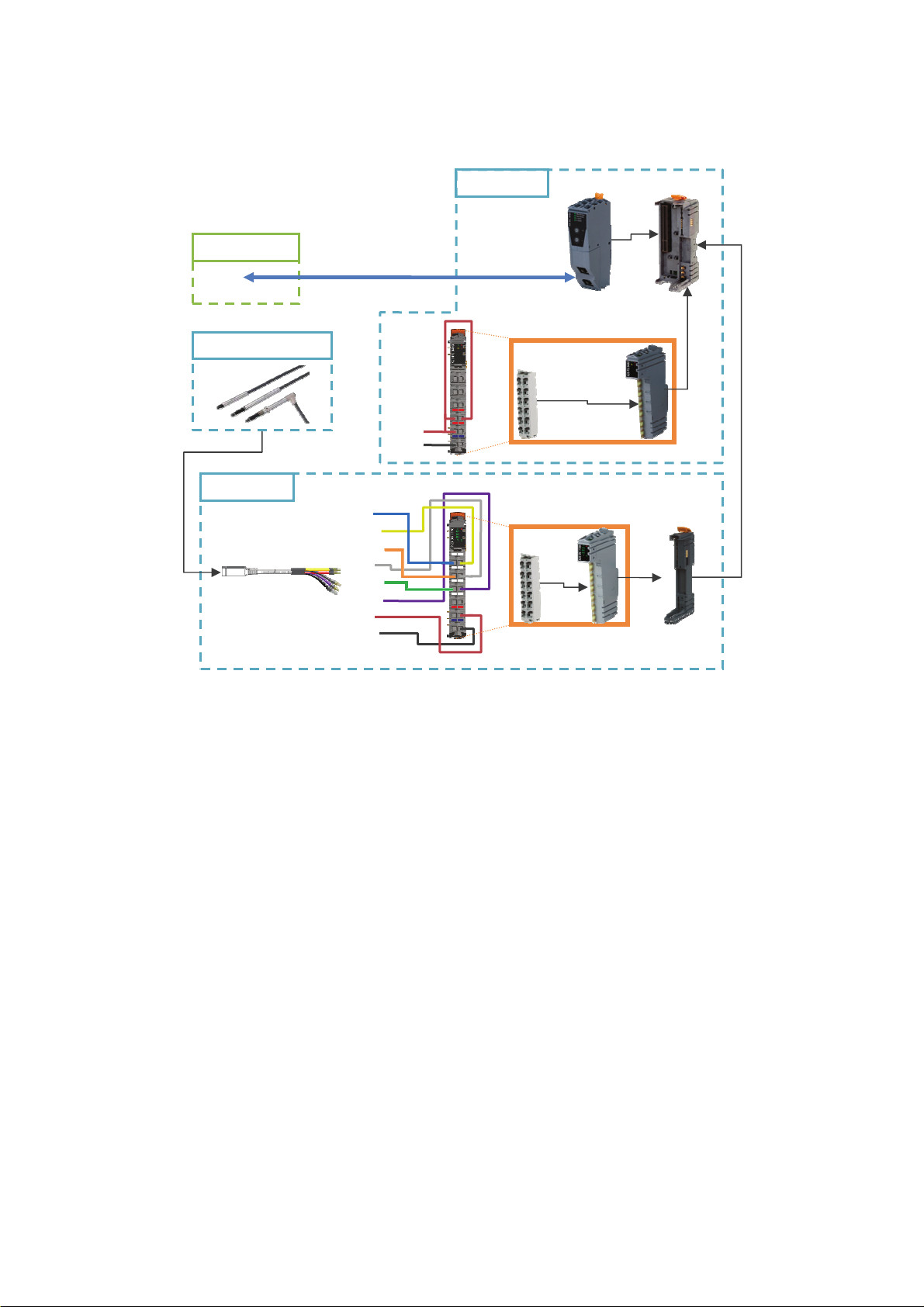
2.2. Equipment connection configuration
Fig 2-2 Adapter side connection diagram
The Ethernet cable used to connect the scanner side and the MG70-EI should be
shielded in accordance with the operating environment. Use a shielded RJ45 (8P8C)
connector as the MG70-EI side connector.
X20BB80
X20PS9400
X20TB12
X20TB12 X20DC11A6
X20BC0088
Ethernet cable
(MG70-EI side: RJ45 connector)
DC24V
GND
Supplied cable
Blue
Yellow
Orange
Gray
Green
Purple
Red
White
MG70-EI
Scanner side
Digital Gauge
MG71-CM
X20BM11

5 (E)
3. Downloading the necessary files
1. Access the Magnescale website
(http://www.magnescale.com/mgs/language/english/), and select:
“Products”
→“Digital Gauge”
→“MG70/71”
→“Software”
Click “Download” of the MG70-EI corresponding to the number of MG71-CM to
be used, and download the file.
2. Save the downloaded file in the appropriate location, and extract the file using
file extraction software.
6 (E)
4. MG70-EI (X20BC0088) main unit settings
4.1. IP address settings
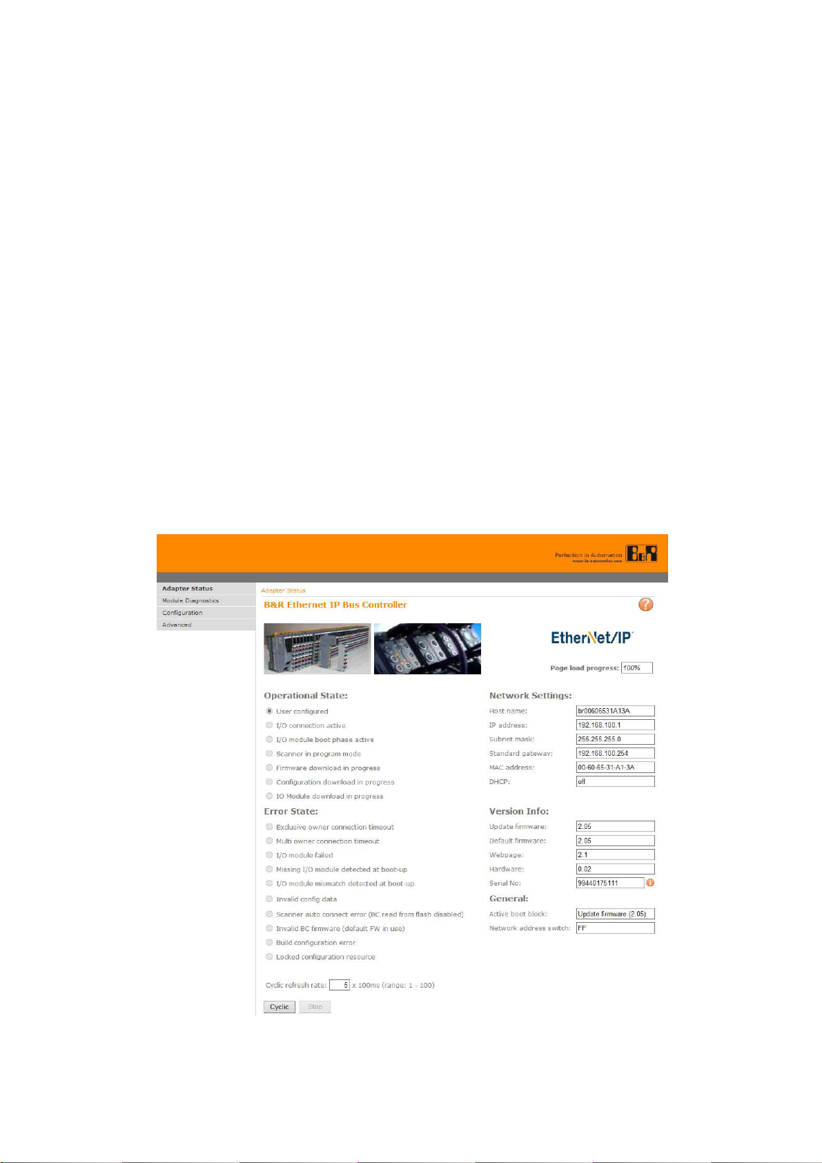
The main unit IP address settings are made using the X20BC0088 Web server
function.
Check the following items before making the settings.
・The number of nodes switch of the X20BC0088 should be set to “0xFF” before
supplying power to the X20BC0088.
・The development computer and the X20BC0088 should not be connected.
* This is to prevent IP address conflict between the development computer and the
X20BC0088.
1. Temporarily set the IP address of the development computer to “192.168.100.2”
and the subnet mask to “255.255.255.0”.
2. Use an Ethernet cable to directly connect the development computer and the
X20BC0088.
3. Start up a Web browser such as Internet Explorer.
4. Enter “192.168.100.1” in the URL field and access that IP address.
This operation enables access of the X20BC0088 Web server.
Fig 4-1 X20BC0088 -- IP address setting -- No.1
7 (E)
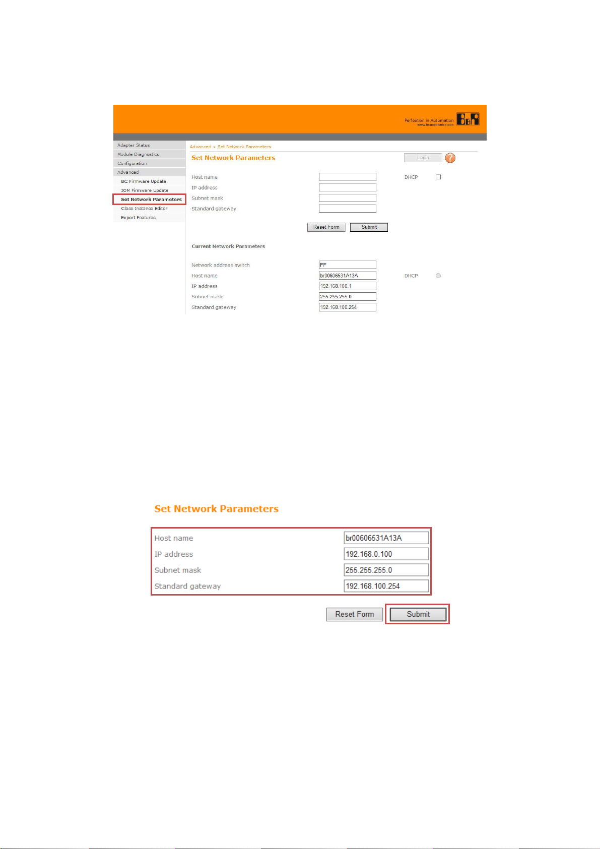
5. Select “Advanced” from the left menu, and select “Set Network Parameters”
from the expanded menu.
Fig 4-2 X20BC0088 -- IP address setting -- No.2
6. Click “Login”.
Set “Username” to “admin” and “Password” to “X20BC0088” , and click “Login”.
* The username and password can be changed from “Advanced” after login.
7. Click “Reset Form”.
The default network parameters are automatically entered.
After that, set “Host name”, “IP address”, “Subnet mask”, and “Standard
gateway” to the desired values (the values to be used with the actual network),
and click “Submit”.
* In the example in this manual, “IP address” is set to “192.168.0.100” and
“Subnet mask” is set to “255.255.255.0”.
When using a router, set “Standard gateway” to the IP address of the router.
Fig 4-3 X20BC0088 -- IP address setting -- No.3
8. Turn off the X20BC0088 power, set the number of nodes switch to “0x00”, and
then turn the power back on again.
9. Set the network parameters of the development computer to arbitrary values
within the range that can be accessed relative to the network parameters set in
step 7 above.
*In this manual, “IP address” is set to “192.168.0.1” and “Subnet mask” is set to
“255.255.255.0”.

8 (E)
10. Enter the IP address set in step 7 above in the URL field of the Web browser, and
check that the X20BC0088 Web server can be accessed.
Also check that the “IP address” and other values of “Network Settings” on the
“Adapter Status” page have been changed to the values set in step 7.
Fig 4-4 X20BC0088 -- IP address setting -- No.4
Inhaltsverzeichnis
Andere Magnescale Aufnahmegeräte Handbücher

Beliebte Aufnahmegeräte Handbücher anderer Marken


Strymon
Strymon NIGHTSKY Bedienungsanleitung

Mitsubishi Electric
Mitsubishi Electric 16CH DIGITAL RECORDER DX-TL5000U Bedienungsanleitung

Tews Technologies
Tews Technologies TPMC465 Bedienungsanleitung

Honeywell
Honeywell Excel 50 Bedienungsanleitung

SeaLevel
SeaLevel COMM+8.LPCI Bedienungsanleitung

Arturia
Arturia AUDIOFUSE STUDIO Bedienungsanleitung


