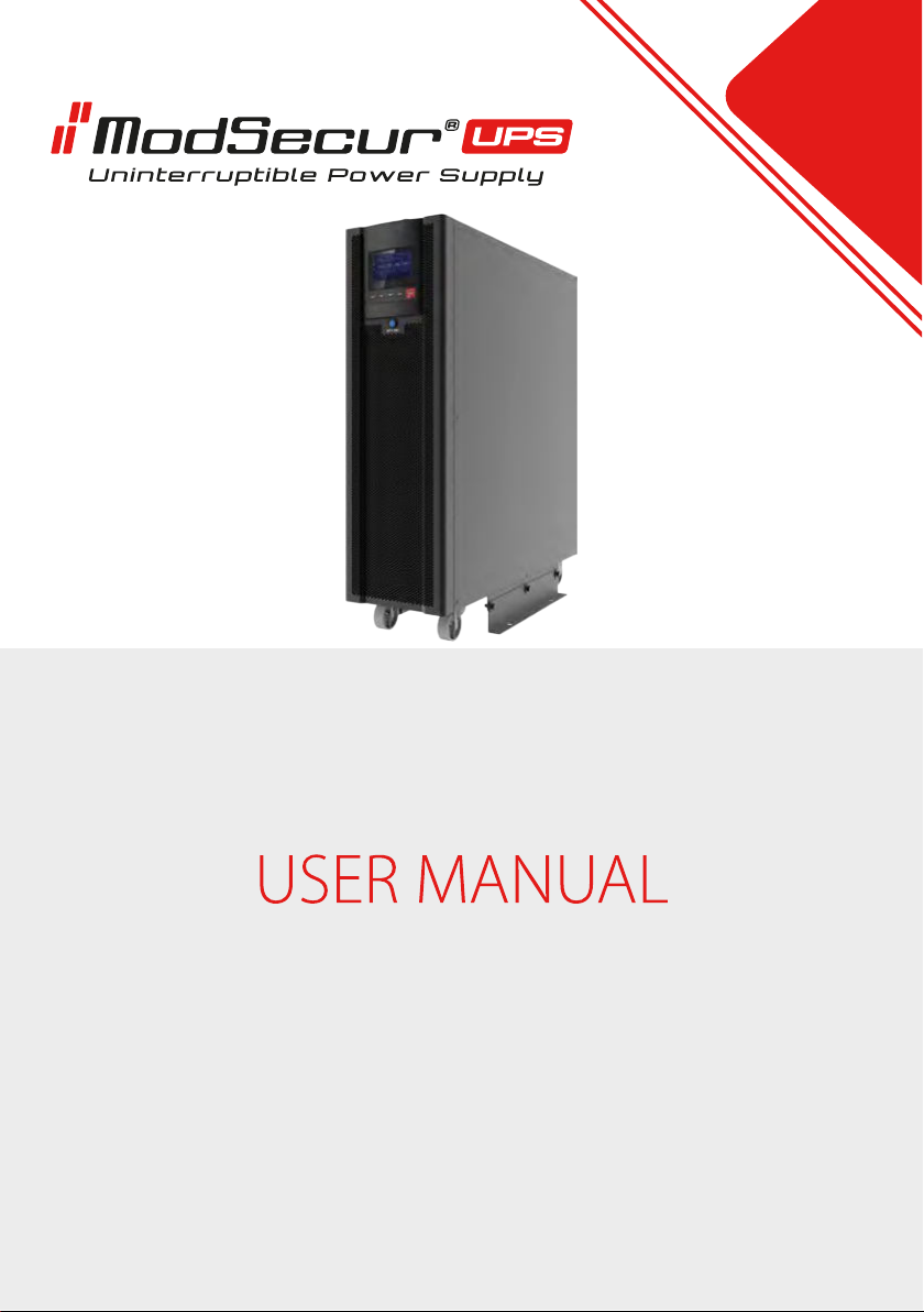
MAXIGLOBAL MODSECUR MT 30 Bedienungsanleitung

MODSECUR MT 30


Table of contents
1. Precautions.......................................................................................................................................1
2. Installation procedure..................................................................................................................3
2.1. Introduction..................................................................................................................................3
2.2 Initial inspection..........................................................................................................................4
2.3. Location.........................................................................................................................................4
2.3.1. UPS room...................................................................................................................................4
2.3.2. Battery room.............................................................................................................................4
2.3.3. Storage........................................................................................................................................5
2.4. Unpacking, checking and setting.........................................................................................5
2.4.1. Unpacking.................................................................................................................................5
2.4.2. The appearance and dimensions of the UPS................................................................7
2.4.3. Service space............................................................................................................................8
2.5. Security elements.......................................................................................................................8
2.5.1. UPS input power......................................................................................................................9
2.5.2. Battery circuit protection.....................................................................................................9
2.6. Power cables..............................................................................................................................10
2.6.1. Maximum power supply currents...................................................................................11
2.6.2. Connecting the AC cables.................................................................................................12
2.6.3. Battery connection...............................................................................................................14
2.7. Communication........................................................................................................................16
2.7.1. Dry Contact IN / OUT communication..........................................................................16
2.7.2. Parallel connection..............................................................................................................20
2.7.3. Communication card slots................................................................................................20
2.7.4. Modbus RTU / RS485 connector.....................................................................................21
3. UPS operation modes................................................................................................................22
3.1. Introduction...............................................................................................................................22
3.2. Principle of operation.............................................................................................................22
3.2.1. Bypass module......................................................................................................................23
3.3. Power supply operation modes..........................................................................................23
3.3.1. Normal operation (On Line)..............................................................................................23
3.3.2. Battery operation..................................................................................................................24
3.3.3. Automatic restart..................................................................................................................24
3.3.4. Electronic bypass..................................................................................................................24
3.3.5. Service bypass.......................................................................................................................24
3.3.6. Economical (ECO).................................................................................................................25
3.3.7. Frequency converter...........................................................................................................25
3.3.8. Parallel operation.................................................................................................................25
4. User manual for the power supply.......................................................................................26
4.1. Power connectors....................................................................................................................26
4.2. Procedures for starting the power supply - single operation..................................27

IV
4.2.2. Running the UPS from the battery.................................................................................27
4.3. Procedures for switching the power supply between operating modes............27

4.3.1. Switching from normal operation to battery mode................................................28
4.3.2. Switching from normal operation to bypass operation.........................................28
4.3.3. Switching from Bypass to normal operation..............................................................28
4.3.4. Switching from the normal operation mode to the Service Bypass mode.....29
4.3.5. Switching from the Service Bypass mode to normal operation.........................30
4.4. Procedure of complete disconnection of the power supply (power supply to
the loads through a mechanical bypass)................................................................................30
4.5. EPO emergency shutdown...................................................................................................30
4.6. Procedures for starting the power supply - parallel operation...............................30
5. LCD panel operation...................................................................................................................31
5.1. Introduction...............................................................................................................................31
5.2. Indications of the UPS operating status on the display.............................................32
5.3. Reading the operating parameters...................................................................................34
5.3.1. Power supply of the bypass line.....................................................................................34
5.3.2. Rectifier track supply...........................................................................................................36
5.3.3. Batteries...................................................................................................................................36
5.3.4. UPS Output.............................................................................................................................37
5.4. Event log......................................................................................................................................37
5.4.1. Device status information (Run info.)............................................................................38
5.4.2. UPS event history..................................................................................................................38
5.4.3. User Log...................................................................................................................................39
5.4.4. Information about the current firmware versions....................................................39
5.5. System configuration settings.............................................................................................40
5.5.1. Configuration of the operating mode and parameters of the power supply.41
5.5.2. Battery settings.....................................................................................................................41
5.5.3. Battery tests............................................................................................................................42
5.6. DryContact contact configuration.....................................................................................43
5.7. Modbus communication settings......................................................................................43
5.8. Display settings.........................................................................................................................44
5.9. Password settings....................................................................................................................44
5.10. Configuration of the UPS operation mode...................................................................45
5.11. UPS cleaning mode...............................................................................................................45
5.12. Saving the history of events to USB memory..............................................................46
5.13. Current alarms........................................................................................................................46
5.14. System speaker.......................................................................................................................47
5.15. ON/OFF......................................................................................................................................47

1
1. Precautions
This user manual contains necessary information on the installation and use of ModSecur
MT30. Before starting the installation and use, please read the manual carefully. The UPS must
be installed and configured by the manufacturer's or distributor's authorized service center. In
the case of installations by persons without the required experience, there is a risk of exposing
users to loss of health or life. Persons not authorized to install may cause damage to the power
supply, which in this case is not covered by the warranty terms.
STANDARDS FULFILLED
The device meets the CE 73/23 and 93/68 (low voltage safety) directives as well as 89/336
(EMC) and the following standards:
*IEC62040-1-1
*IEC/EN62040-2 EMC CLASS C3
*IEC62040-3
CAUTION - High leakage current
The connection of the protective conductor (PE) is essential and must be made before
connecting the other working conductors (power supply, receiving, battery). Earthing should
be performed in accordance with the prevailing standards and practical knowledge in the
place of installation. The leakage current is greater than 3.5mA and less than 1000mA. When
selecting immediate action RCCB or RCD devices, take into account the transient and steady
state leakage currents that may occur during commissioning of the device. Select residual
current circuit breakers (RCCBs) that are sensitive to DC unidirectional pulses (Class A) and not
sensitive to transient current pulses. It should also be remembered that a given RCCB or RCD
device conducts leakage currents of the receiver.
Service
Dangerous voltage exists in the UPS housing. The risk of contact with such voltage is kept to
a minimum as the live parts are located behind the closed housing. Additional internal
protective covers ensure that the device is protected in accordance with the protection class
IP20. Normal operation of the device, taking into account the recommended operating
procedures, does not pose any threat to the personnel. All maintenance and service procedu-
res require access to the interior of the unit and should only be performed by trained person-
nel.

2
High battery voltage > 400 Vdc
All work related to the maintenance and installation of batteries may be performed by a
properly trained service. When the batteries are connected, the voltage across their terminals
exceeds 400 Vdc and is potentially lethal. Battery manufacturers provide detailed precautions
that must be observed when working on or in the vicinity of large battery batteries. Such
measures must always be strictly adhered to. Particular attention should be paid to the
recommendations regarding local environmental conditions and the provision of protective
clothing, first aid and fire fighting equipment.

3
2. Installation procedure
This chapter is devoted to the method of installation, mounting and wiring of the UPS.
2.1. Introduction
This chapter presents the basic requirements for the location and cabling of the power
supply. The description presents a step-by-step installation manual, which is a series of guide-
lines that should be followed by the service when installing the device.
Warning - Installation may only be performed by an authorized service center
1. Do not connect electrical appliances to the power supply until the service technician has
verified that the power supply is properly connected and configured.
2. The UPS should be installed by qualified technical personnel in accordance with the guide-
lines contained in this chapter.
Do not perform any electrical work interfering with the electrical system upstream and
downstream of the UPS while the UPS system is operating. Damage resulting from this (eg
change of the phase sequence) is not covered by the warranty.
Warning: Dangerous Batteries
Particular precautions must be taken when working with batteries connected to the power
supply. When the battery is connected, the terminal voltage exceeds 400 Vdc and is poten-
tially lethal.
To protect the eyes against an accidental electric arc, it is recommended to wear protective
glasses. Additionally, it is recommended to:
Remove rings, watches and all metal items
Only use tools with insulated handles.
If the battery leaks or is otherwise damaged, it must be replaced. Damaged batteries should
be stored in a sulfuric acid resistant container and disposed of in accordance with local regula-
tions.
If the electrolyte comes into contact with the skin, wash the contaminated area immediately
with water.

4
2.2. Initial inspection
Please perform the following checks prior to installation:
- Visually check that the delivered devices, i.e. the UPS and the batteries, have not been dama-
ged during transport. Any damage found should be reported to the supplier immediately.
- Verify the compliance of the supplied equipment with the installation requirements. The
power of the power supply is each time described on the label.
2.3. Location
2.3.1. UPS room
The UPS is intended for indoor installation. The device should be placed in a clean environ-
ment with adequate ventilation to keep the ambient temperature within the required specifi-
cation range. The UPS provides forced convection cooling through internal fans. Cold air
enters the device through the vents at the front of the housing and is blown out through the
grills at the rear of the housing. Do not block the ventilation openings.
Depending on the room conditions, the ventilation openings of the power supply should be
regularly cleaned, e.g. with a vacuum cleaner. The accessibility of ventilation will ensure
efficient cooling and extend the life of the device.
Note: The UPS should be installed on a stable and non-flammable surface.
2.3.2. Battery room
The battery temperature should be stable as it is the main parameter influencing the battery
life and capacity. The optimal operating temperature of the battery is 15-25 ° C. It is recom-
mended to maintain a nominal temperature of 20 ° C.
Working at higher temperatures shortens the battery life, and working at lower temperatures
reduces their capacity. Each increase of the battery operating temperature by another 8 ° C
reduces the service life by 50%.
Keep batteries away from heat sources and hot air vents.
When installing the battery outside the UPS, use the battery circuit protection located as close
to the battery as possible. Keep the cables connecting the battery and the UPS as short as
possible.

5
2.3.3. Storage
If the device is not installed and needs to be stored, it should be protected against excessive
moisture and high temperature. Batteries should be stored in a dry and cool room. The most
suitable storage temperature for the battery is 20-25 ° C. If the appliance is not installed imme-
diately after delivery, it should be stored indoors so that it is protected from excessive moistu-
re and heat sources.
2.4. Unpacking, checking and setting
Before unpacking, carefully inspect the delivered packaging of the device to make sure that it
has not been damaged during transport. After removing it from the packaging, check that the
equipment has no signs of damage. If there is any damage, report it to the supplier immedia-
tely.
2.4.1. Unpacking
The power supply is delivered in a cardboard box on a wooden pallet. To unpack, remove the
cardboard packaging and protective foams inside the packaging. The following shows the
device after removing the packaging.
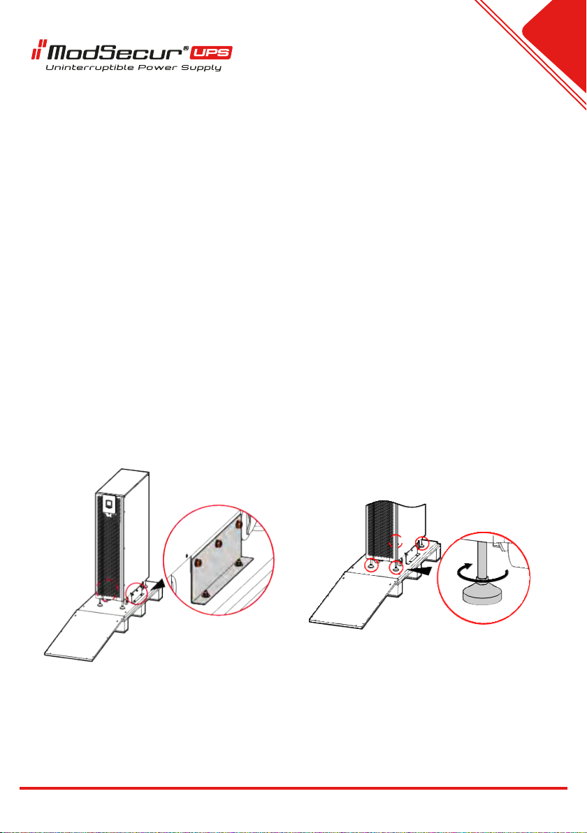
View of an exemplary power supply after removing the packaging

6
Tip: Remove the screws connecting the UPS housing with the wooden pallet, and screw in
the feet stabilizing the UPS, and then place the UPS at the installation point, using the exit
provided in the UPS housing. Disassembly should be done carefully so as not to damage the
housing.
Please check the supplied equipment for correctness on the label located on the top cover of
the UPS. The label provides basic information about the model, power, etc.
Note: The protective materials remaining after dismantling (wood, plastic, etc.) must be dispo-
sed of in accordance with the applicable local environmental regulations.
In order to extend the life of the device, it is necessary to provide a suitable place for its
installation, which should guarantee:
- Easy to connect to the electrical installation
- Sufficient space for handling
- Ventilation or air conditioning to ensure adequate cooling of the power supply
- Protection against corrosive gases and vapors
- Protection against excessive moisture and heat sources
- Protection against dust, dirt and other contaminants
- Adequate fire protection
- Working temperature should be in the range of 20-25ºC. At this temperature, the batteries
perform at their optimum.
Inhaltsverzeichnis
Andere MAXIGLOBAL UPS Handbücher
Beliebte UPS Handbücher anderer Marken

Pylontech
Pylontech Victron & Pylontech US5000 Bedienungsanleitung

Tecnoware
Tecnoware EVO DSP PLUS MM 6.8 Bedienungsanleitung

Mecer
Mecer ME-1000-WTU Bedienungsanleitung

Mustek
Mustek PowerMust 530(B) Plus Installations- und Betriebshandbuch

Emerson
Emerson Liebert NXL series Bedienungsanleitung

MAKELSAN
MAKELSAN BOXER SERIES Bedienungsanleitung