- 2 -
CONTENTS
SECTION DESCRIPTION PAGE
1. Warnings ............................................................................................................................................ 3
1.1 General warnings ............................................................................................................................... 3
2. Technical data ................................................................................................................................... 4
2.1 Gas appliances................................................................................................................................... 4
3. Installation diagrams ......................................................................................................................... 5
3.1 Direct ”Combined” gas oven FGMD67/FGMD67SC....................................................................... 5
3.2 Direct ”Combined” gas oven FGMD67/FGMD67SC with stand SF3 .............................................. 7
3.3 Direct ”Combined” gas oven FGMD107/FGMD107SC with cabinet SFA - SFRU.......................... 8
3.4 Direct ”Combined” gas oven FGMD207/FGMD207SC with stand SF2.......................................... 9
4. Installation instructions .................................................................................................................... 10
4.1 Preparing for installation................................................................................................................... 10
4.1.1 Laws, regulations and technical directives ....................................................................................... 10
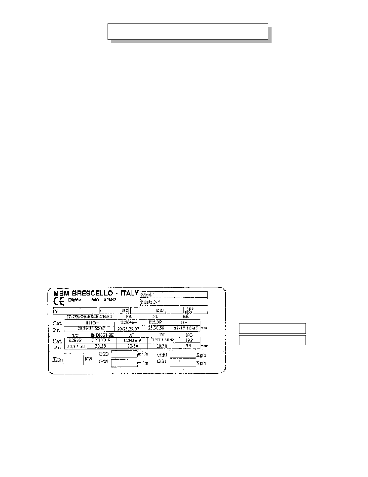
4.1.2 Plate to E.U. standards....................................................................................................................... 10
4.2 Positioning ........................................................................................................................................ 11
4.3 Cold water connection ...................................................................................................................... 11
4.4 Waste water outlet ............................................................................................................................. 11
4.5 Electrical connection ........................................................................................................................ 12
4.5.1 Earthing ............................................................................................................................................. 12
4.5.2 Equipotential system......................................................................................................................... 12
4.5.3 Power supply cable............................................................................................................................ 12
4.5.4 Cable wiring to terminal block ......................................................................................................... 12
4.6.0 Table I gas, pressure and classes in different countries ..................................................................... 13
4.6 Hook-up with the gas system ............................................................................................................ 14
4.6.1 Transformation for operation with a different type of gas ................................................................ 14
4.6.1.1 Replacing burner nozzle (FGMD67, FGMD67SC, FGMD107 and FGMD107SC) ......................... 14
4.6.1.2 Replacing burner nozzle (FGMD207 and FGMD207SC) ................................................................ 15
4.6.1.3 Adjusting gas pressure at the burner ................................................................................................. 15
4.6.1.4.1a Table II: gas burner injectors for direct ovens................................................................................... 18
4.6.1.4.1b Table III: gas burner injectors for direct ovens.................................................................................. 19
4.6.1.4.1c Table IV: gas burner injectors for direct ovens.................................................................................. 20
4.6.1.5 Checking heat capacity by means of pressure .................................................................................. 21
4.6.1.6 Discharging the products of combustion under a suction hood ....................................................... 21
4.6.1.7 Discharging the products of combustion using a flue ......................................................................21
4.6.1.8 Type of installation for discharging the products of combustion .................................................... 21
4.6.1.9 Other outlets ...................................................................................................................................... 23
4.7 Room ventilation .............................................................................................................................. 23
5. Use ..................................................................................................................................................... 23
5.1 User instructions: commissioning..................................................................................................... 23
6. Using the electronic oven ................................................................................................................. 25
6.1 Cooking selection ............................................................................................................................. 25
6.2 Vent valve in cooking chamber ........................................................................................................ 25
6.3 Humidifier ......................................................................................................................................... 26
6.4 Chamber light.................................................................................................................................... 26
6.5 Fan speed ........................................................................................................................................... 26
6.6 Cooking chamber temperature .......................................................................................................... 26
6.7 Cooking time and starting the oven ................................................................................................. 26
6.8 Core probe ......................................................................................................................................... 27
6.9 Cook & Hold ..................................................................................................................................... 27
6.10 Displaying and modifying cooking parameters ............................................................................... 27
6.11 Messages and alarms ......................................................................................................................... 28
7. Cleaning and Maintenance ............................................................................................................... 28
7.1 Cleaning ............................................................................................................................................ 28
7.1.1 Cleaning after cooking and at the end of the day............................................................................. 28
7.1.2 Troubleshooting................................................................................................................................29
7.2 Maintenance...................................................................................................................................... 29
7.2.1 Replacing components...................................................................................................................... 29
A) Electric components and electronic card ..................................................................................... 29
B) Burners.......................................................................................................................................... 29
C) Detection device........................................................................................................................... 29
D) Ignition devices ............................................................................................................................ 29
E) Gas multi-functional valves.......................................................................................................... 29
F) Oven lamp ..................................................................................................................................... 30
G) Oven door gasket.......................................................................................................................... 30
H) Cleaning solenoid valve filters .................................................................................................... 30
7.2.2 Yearly maintenance ........................................................................................................................... 31
7.2.3 Safety devices Equipment control and safety systems .................................................................... 31
7.3 Switching off in the event of equipment faults................................................................................. 31
7.3.1 Precautions if the oven is not to be used for a lengthy period.......................................................... 32