MCS MCS-Magnum Betriebsanleitung
Revision 2.05B
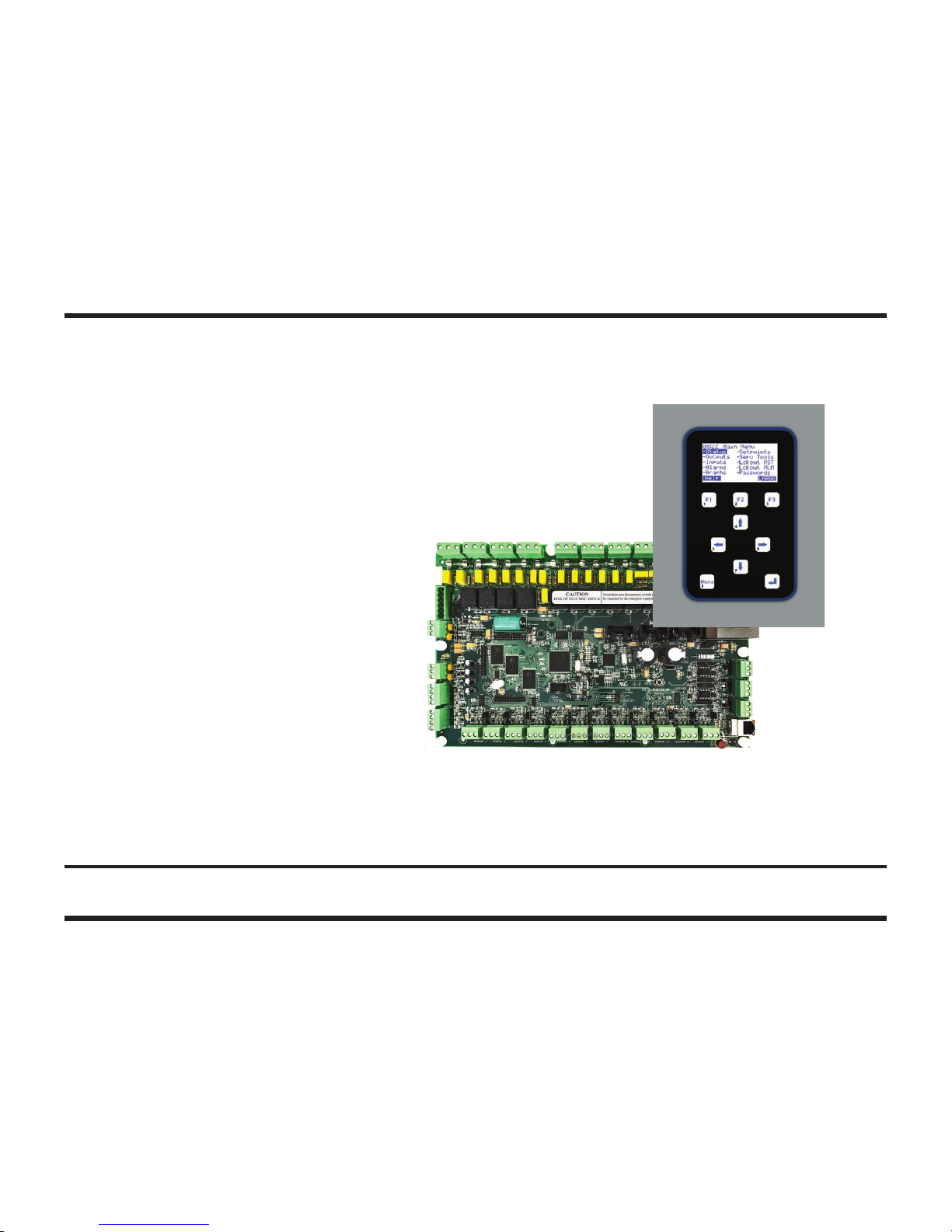
MCS-Magnum Controller System
Simplied Description and Troubleshooting
Plus MCS-MAGNUM Alarms and Safeties
Revision 2017-11-07

2
The MCS Commitment
Our commitment is to provide practical solutions for the industry’s needs and to be both
a leader and a partner in the effective use of microprocessor controls.
Micro Control Systems, Inc.
5580 Enterprise Parkway
Fort Myers, Florida 33905
USA
Phone: (239) 694-0089
Fax: (239) 694-0031
www.mcscontrols.com
Information contained in this manual has been prepared by Micro Control Systems, Inc. and is company
condential and copyright ©protected 2017.
Copying or distributing this document is prohibited unless expressly approved by MCS.

3
Table of Content
MCS-MAGNUM CONTROLLER TROUBLESHOOTING
1.1. Troubleshooting General Dead Board Symptoms.........................................................................................................................................................6
1.2. Troubleshooting Sensor Input Problems.......................................................................................................................................................................7
1.3. Troubleshooting Relay Output Problems ......................................................................................................................................................................8
Appendix A
1.4. Entering Authorization Codes to Log In and Out of a Magnum.....................................................................................................................................9
Appendix A (continued)
1.5. Entering Authorization Codes to Log In and Out of a Magnum...................................................................................................................................10
Appendix B
1.1. Manually Turning On and Off a Magnum Relay Output ..............................................................................................................................................11
Appendix B (continued)
1.2. Manually Turning On and Off a Magnum Relay Output ..............................................................................................................................................12
Appendix C
1.1. Determining and Changing the Network Address of a Magnum .................................................................................................................................13
Appendix C (continued)
1.2. Determining and Changing the Network Address of a Magnum .................................................................................................................................14
Appendix D
1.1. Sensor Input Reference Table.....................................................................................................................................................................................15
Appendix D (continued)
1.2. Sensor Input Reference Table.....................................................................................................................................................................................16
Appendix E
1.1. Analog Sensor Input Reference Table ........................................................................................................................................................................17
Appendix F
1.1. MCS-UPC Status LED Code Descriptions..................................................................................................................................................................18
Magnum Alarms and Safeties
1.1. There are four types of alarms that are generated by the Magnum control logic:.......................................................................................................19
1.2. Information Only Alarms..............................................................................................................................................................................................19
1.2.1 System Generated Alarms.................................................................................................................................................................................19
1.2.2 User Initiated Alarms..........................................................................................................................................................................................20
1.2.3 Automatic Alarms...............................................................................................................................................................................................20
1.3. Magnum System Alarms .............................................................................................................................................................................................20
1.3.1 Conguration Alarms .........................................................................................................................................................................................20
1.3.2 MCS Local Network Alarms ...............................................................................................................................................................................21
1.3.3 Key Sensors Alarms ..........................................................................................................................................................................................21
1.3.4 Emergency Stop Alarm ......................................................................................................................................................................................21
1.4. Setpoint safety alarms.................................................................................................................................................................................................21
1.4.1 Sensor Inputs Used With Magnum Setpoint Safeties:.......................................................................................................................................22
1.4.2 Setpoint safeties................................................................................................................................................................................................22
1.5. TurboCor Compressor Alarms.....................................................................................................................................................................................24

4
MCS-MAGNUM CONTROLLER TROUBLESHOOTING
5
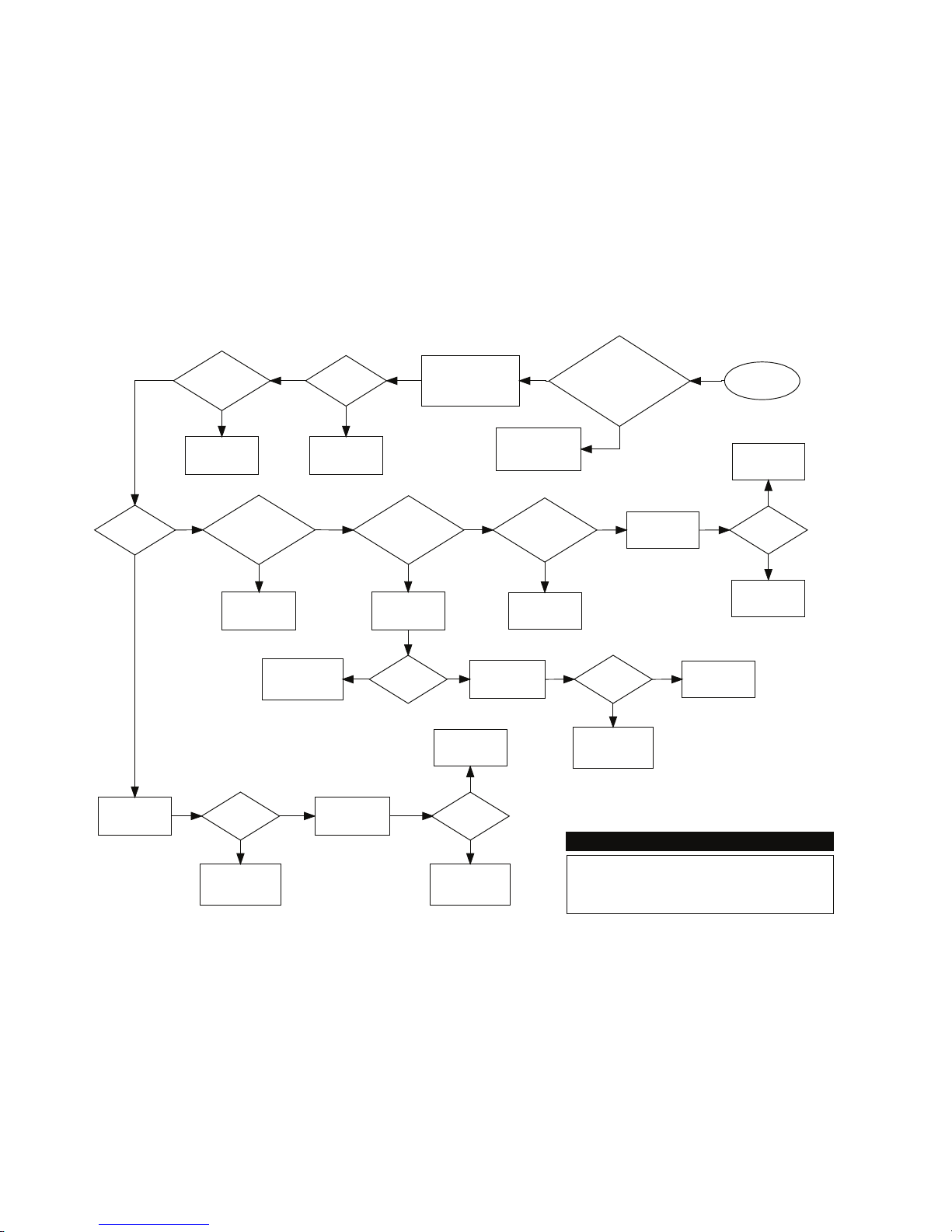
Measure voltage at ac
input connector block and
verify that it is within 10
percent of rated voltage
Troubleshooting General Dead
Board Symptoms
Voltage
ok?
Ac input
fuse blown?
Replace fuse. If
fuse blows again
replace board
Correct ac supply
to board
Start
Press RESET
button on board
Is red RESET
light on all the
time?
Is green
16VDC light
on?
Magnum Micro Controller Systems
If board has a
voltage selector
switch, is it set
correctly?
Turn power off, set
switch to correct
voltage, turn power on
Turn power off, wait
10 seconds, turn
power back on
Board was locked up
due to momentary
power dip or spike
Problem
solved?
Board was locked up
due to momentary
power dip or spike
Replace board
Is board a
Magnum?
Problem
solved?
Press RESET
button on board
Turn power off, wait
10 seconds, turn
power back on
Board was locked up
due to momentary
power dip or spike
Problem
solved?
Board was locked up
due to momentary
power dip or spike
Problem
solved? Replace board
Replace board
Is LCD
backlight on? Try to reload
software Problem
solved?
Replace board
Software was
corrupted
Yes
Yes
Yes
Yes Yes
Yes
Yes
Yes
Yes Yes
Yes
Replace board
Yes
No
No
No
No No
No
No
No
No
No
No
1.1. Troubleshooting General Dead Board Symptoms

6
Start
Are ALL sensors
on the board not
responding?
Go to any sensor input
on the board and
measure dc voltage
from +5 pin to ground
4.75 to 5.25
volts dc?
Yes
Remove all sensor blocks
from board, wait 10 seconds,
then measure dc voltage
from +5 pin of any sensor
input on board to ground
No
4.75 to 5.25
volts dc?
Turn power off to board
and measure for short
from +5 pin of any sensor
input on board to ground
No
Shorted?
Replace board
No
Board is defect and may
have been damaged by
overvoltage applied to a
sensor input
Replace board
Yes
Go to defect sensor input
and remove connector
block
üü
correctly?
No
Defect sensor or
wiring to sensor
Yes
Yes
Yes
Board is defect and may
have been damaged by
overvoltage applied to
the sensor input
If system uses expansion boards,
verify MCS-I/O communication by
seeing if red TX light blinks on all
boards and also check for proper
address jumper settings on all
expansion boards
Check that all sensor input
Analog / Digital jumpers
are set correctly and all
sensors are set to AUTO
No
If ANALOG sensor, connect
MCS-SENSOR-TEST block (100K ohm
1/4 watt resistor from +5 pin toSI pin on
connector base) and compare sensor
reading to Appendix J
If DIGITAL sensor,
connect jumper wire from
+5 pin to SI pin on
connector base and see if
sensor reading changes
from ON to OFF or OFF to
ON
Troubleshooting Sensor
Input Problems
Magnum Micro Controller Systems
Reconnect Sensor 1 and
measure dc voltage from
+5 pin of any sensor
input on board to ground
4.75 to 5.25
volts dc?
The sensor or wiring to
sensor you just
reconnected is shorted
to ground
Reconnect the next sensor
and measure dc voltage
from +5 pin of any sensor
input on board to ground
Yes
No
1.2. Troubleshooting Sensor Input Problems

7
Start
Are ALL relays
on the board not
responding?
Turn power off,
wait 10 seconds,
turn power back on
All relays
work now?
Yes Replace board
Go to defect relay
output, remove
connector block and set
relay to MANOFF
At the connector base
is there less than 1
ohm of resistance
beween COM and
NC?
No
Set relay to
MANON
Yes
If system uses expansion boards,
verify MCS-I/O communication by
seeing if red TX light blinks on all
boards and also check for proper
address jumper settings on all
expansion boards
Check that all relays
are set to AUTO
(See Appendix H)
No
No
Board was locked up
due to momentary
power dip or spike
Yes
Is the relay
output fuse
blown? Replace board
No
Replace fuse and set relay to
AUTO If fuse blows again after
putting system back into normal
operation, problem is due to
defect outbound control device
or a short in the wiring.
Yes
At the connector base
is there less than 1
ohm of resistance
between COM and
NO?
Replace board
No
Board is ok. Set relay to AUTO and
check wiring from relay output
connector block to outbound controlled
device. Also, if board is a MCS-I/O or
RO8 refer to Appendix K for possible
snubber network leakage issues and
how to overcome them.
Yes
Troubleshooting Relay
Output Problems
Magnum Micro Controller Systems
1.3. Troubleshooting Relay Output Problems

8
1.4. Troubleshooting Lost I/O Communication Problems
9
Start
Is TX I/O light
on the Magnum
blinking?
Locate expansion
board where TX
LED is not blinking
Does board
have power?
Replace fuse. If fuse
blows again, replace
expansion board
Ac input
fuse blown?
No
Yes
Replace expansion
board
Yes
Check wiring to ac
input block
No
No
Verify that MCS I/O
termination jumper is
on first and last board
only
On Magnum board,
turn power off, swap
chips U12 and U13,
turn power back on
No
Yes
Does TX light on
at least ONE
expansion board
blink?
Yes
Yes
On Magnum board,
turn power off, swap
chips U12 and U13,
turn power back on
Does TX light on at
least ONE
expansion board
blink?
No
Chip that was in
U12 is defect
Yes
Replace Magnum
board
No
Verify that address
jumpers on all
expansion boards are
set correctly
Turn power
off to
Magnum for
10 seconds,
turn power
back on
Does TX I/O light
on the Magnum
blink now?
Magnum was locked
up due to momentary
power dip or spike
Troubleshooting Lost I/O
Communication Problems
Magnum Micro Controller Systems
Replace Magnum
board
No
Yes
Does TX I/O light
on the Magnum
blink now?
Chip that was in
U12 is defective
Verify that MCS I/O
wiring between boards
is correct, especially
polarity

9
Appendix A
1.5. Entering Authorization Codes to Log In and Out of a Magnum
First, at the Main Menu use the arrow keys to navigate to Passwords:
Next, press the Enter key. You will see the following:
Now enter the proper four-digit authorization code. Each - is changed to a
*as numbers are entered. After you have keyed in the numbers,
press the Enter key.
09:56 Main Menu
-Status -Setpoints
-Outputs -Serv Tools
-Inputs -Lckout RST
-Alarms -Lckout ALM
-Graphs -Passwords
Help
09:56 Password
Enter Pin
- - - -
Then Press ‘ ‘ Key
F1 F2 F3
09:56 Password
Enter Pin
****
Then Press ‘ ‘ Key
F1 F2 F3

10
Appendix A (continued)
1.6. Entering Authorization Codes to Log In and Out of a Magnum
The Magnum will tell you if it accepted your code and the level of authorization.
For example,
if you entered a valid factory authorization code you will see the following:
If you entered an invalid authorization code you will see the following:
Once you are logged in you can log out immediately by simply entering any invalid
authorization code. If you are logged in and no keys are pressed for more than 15
minutes the Magnum will automatically log you out, warning you shortly before with how
many seconds remaining as shown here:
09:56 Password
Level – VIEW ONLY
Invalid
Pin
Then Press ‘ ‘ Key
F1 F2 F3
Press Any Key
to Avoid
Auth Log Out
60
09:56 Password
Level – Factory
Then Press ‘ ‘ Key
F1 F2 F3
Inhaltsverzeichnis
Andere MCS Controller Handbücher


