
As at 11/03 2
Chapter 7: Switch actuators
7. 5 Switch actuator 8-fold
Switch actuator REG-K/8x230/16 with manual mode
Art. No. 6478 93
½Caution:
Adjacent devices can be damaged! Only install
devices with at least basic insulation next to the
device.
Snapping onto the DIN rail (Fig. "):
1Place the device on the DIN rail from underneath
and push upwards (press the springs together)
2Press down at the top and hook onto the rail
|A data rail is not required.
Removal from the DIN rail (Fig. "):
3Push the device upwards (press the springs toge-
ther).
4Unhook the device from the DIN rail at the top and
remove the device
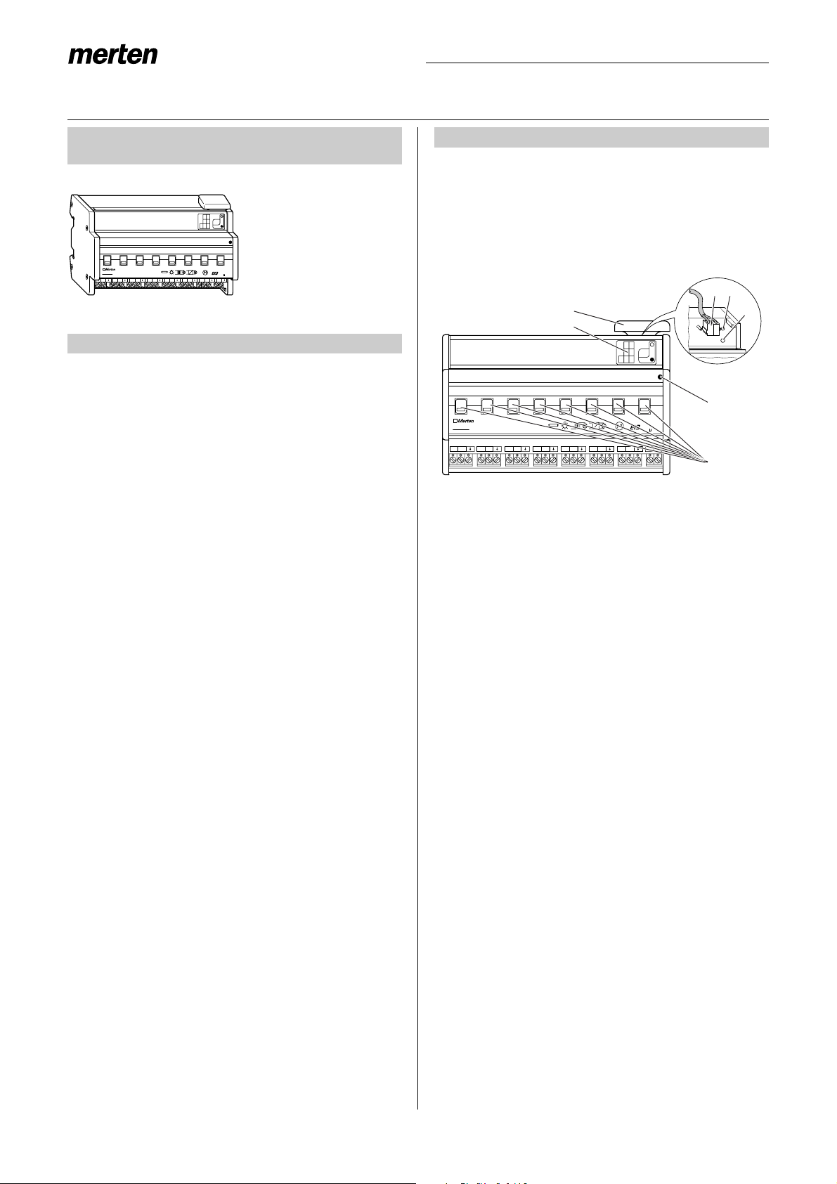
Bus connection (Fig. §):
1Connect the red bus wire to the red terminal (+)
and the black wire to the dark grey terminal (-).
2Shield and filler wire as well as the white and yel-
low wires of the bus cable are not required. Insula-
te and place in the cable cover
3Place the cable cover on the bus connection
4Close the flap
½Caution:
Safety clearance must be guaranteed in accor-
dance with DIN VDE 0110 part 1. A distance of
at least 4 mm must be maintained between in-
dividual cores of the 230 V cable and the bus ca-
ble.
Connection of the outputs:
¼Danger due to electrical current:
Vibrations during transport can enable the out-
puts. When connecting the mains voltage to the
system, voltage can lie at the outputs!
To de-energise the outputs:
After commissioning, carry out a switching cyc-
le (On/Off) via bus telegrams or set the manual
switch to “OFF”.
½Caution:
Switch actuator can be damaged. Protect the
switch contacts with a series-connected 16 A
circuit-breaker.
Connect the device according to the connection ex-
ample. The cables to the loads as well as the system
voltages (L1, L2 or L3) are connected via screw termi-
nals for max. 16 A. Every two L connections are
bridged internally.
(See Fig. %)
After wiring the device, the assignment of the physical
address and the parameterisation are carried out:
1Connect the interface to the bus
2Connect the bus voltage to the system
3Press the programming button in the device (red
LED lights up)
4Download the physical address from the ETS via
the interface (red LED is extinguished)
5Download the prepared application with the appro-
priate parameter settings into the device via the in-
terface (green LED lights up)
6Connect the mains voltage to the system
7When the device is ready for operation, check the
required function (also possible using ETS)
2. Installation
1
2
3
4
"
Bus
§
1
4
2
3
Bus
3. Commissioning
$


/6 Bedienungsanleitung")


