Micas M2-W6510-48V8C Installations- und Betriebsanleitung

M2-W6510-48V8C Switch
Hardware Installation and Reference Guide
Version V1.0
copyright © 2023 Micas

Copyright Statement
Micas Networks © 2023
Micas Networks reserves all copyrights of this document. Any reproduction, excerption, backup, modification,
transmission, translation or commercial use of this document or any portion of this document, in any form or by any means,
without the prior written consent of Micas Networks is prohibited.
Exemption Statement
This document is provided “as is”. The contents of this document are subject to change without any notice. Please obtain
the latest information through the Micas Networks website. Micas Networks endeavors to ensure content accuracy and
will not shoulder any responsibility for losses and damages caused due to content omissions, inaccuracies or errors.

Preface
Thank you for using our switches. This guide will help you install and use the switches.
Scope
This manual describes the functions and physical features of the switches, and presents the installation procedure,
troubleshooting procedure, technical specifications, and specifications and usages rules of cables and connectors. It is
intended for the users that have some experience in installing and maintaining network hardware and want to learn the
above information. At the same time, it is assumed that the users of this switch are already familiar with the related
terms and concepts of Ethernet.
Document Structure
Chapter 1 "Product Overview" describes the main characteristics, technical specifications, and related modules
of this product.
Chapter 2 "Preparation before Installation" lists the safety, power supply, and site requirements that must be
met before the switch can be installed.
Chapter 3 "Product Installation" describes how to install the integrated switch and modules, and connect its
power cables and grounding lines.
Chapter 4 "System Debugging" describes the commissioning after the switch is powered on for the first time.
Chapter 5 “Monitoring and Maintenance”
Chapter 5 "Troubleshooting" describes possible problems met during the installation and use of the switch and
solutions for such problems.
Appendix A "Connector and Connection Media"
Appendix B “Lightening Protection”
Appendix C “Cabling Recommendations in Installation”
Appendix D “Site Selection”
Obtaining Technical Assistance
Micas Networks Website: https://www.micasnetworks.com/
Technical Support Website: http://www.micasnetworks.com/support
Case Portal: http://www.micasnetworks.com/case
Community: http://www.micasnetworks.com/company/contact
Technical Support Email: [email protected]
Related Documents
Documents
Description
Configuration Guide
Describes network protocols and related mechanisms that supported by the
product, with configuration examples.
Command Reference
Describes the related configuration commands, including command modes,
parameter descriptions, usage guides, and related examples.

Symbol Conventions
Means reader take note. Notes contain helpful suggestions or references.
Means reader be careful. In this situation, you might do something that could result in equipment damage or loss
of data.

Hardware Installation and Reference Guide
- 3 -
1 Product Overview
M2-W6510-48V8C switch is data center oriented high density 10G/25G access switch, providing 25G/100G access, low
latency, and complete data center features. M2-W6510-48V8C switch, with up to 48 25G ports and 8 100G ports, can
be used to compose a high-performance and high-reliability data center network.
The M2-W6510-48V8C Switch:
Model
100G
QSFP28
Ethernet
Port
25G/10G
SFP28
Ethernet Port
10GBase-T
Ethernet Port
Extension
Module Slot
Redundant
Fan
Redundant
Power Supply
M2-W6510-48V8C
8
48
N/A
N/A
3+1
1+1
An SFP28 port supports 25G/10Gbase-R and does not support 1000base-X.
A QSFP28 port supports both 100G/40G mode and 4x25G/4x10G mode.
Specifications
Model
M2-W6510-48V8C
CPU
Intel Xeon D-1527, quad-core eight-thread processer, 2.2GHz, LLC Cache 6M
BOOT ROM
16MB
SSD
240GB
SDRAM
DDR4 8GB (Compatibility: 32GB)
Extension Module
Slot
Unsupported
Extension Module
Unsupported
Fan Slot
4 (support 3+1 redundancy, configure at least 3 fan modules with same air channel direction in
one switch)
Fan Module
Port-to-PSU: M1HFAN III-F
PSU-to-Port: M1HFAN III-R
Power Supply
Slot
2 (support 1+1 redundancy)
Power Module
Port-to-PSU: PA550II-F
PSU-to-Port: PA550II-R
Power Supply
Input
AC input
Rated voltage range: 100V AC to 240V AC
Maximum voltage range: 90V AC to 264V AC
Frequency: 50 Hz to 60 Hz
Rated current: 3.5A to 7.2A
Power
Consumption
Less than 300 W
SFP28 Port
Supported

Hardware Installation and Reference Guide
- 4 -
QSFP28 Port
Supported
FC Port
Unsupported
10GBASE-T Port
Unsupported
Temperature
Warning
Support temperature warning and over-temperature protection.
EMC Standards
Emissions: FCC part15 Subpart B, EN55032, EN61000-3-2, EN61000-3-3 or EN61000-3-11, E
N61000-3-12 (as applicable)
Immunity: EN55035
Emissions and Immunity: EN300386
Safety Standards
UL/CSA 62368-1, EN 62368-1, IEC 62368-1 CB Scheme with all country differences
Working
Temperature
0°C to 45°C (32°F to 113°F)
Storage
Temperature
-40°C to 70°C (-40°F to 158°F)
Working Humidity
10% to 90% RH (non-condensing)
Weight
Net weight: 8 kg (including 4 fan modules and 2 power modules)
Dimensions
(L x W x H)
442 mm x 560 mm x 43.1 mm, 1RU
M2-W6510-48V8C switch is a class A product. In a domestic environment, this product may cause radio
interference in which case the user may be required to take adequate measures.
The 25G/100G Ethernet port of the M2-W6510-48V8C switch supports DAC.
Product Appearance
The hardware of the W6510-48V8C includes the chassis, the power supply system and the heat dissipation system.
The power supply system: Provides two power supply slots, which support 1+1 power supply redundancy. It is
recommended users configure power supply redundancy.
The heat dissipation system: Provides four fan module slots, which support 3+1 fan redundancy. It is
recommended users configure all fans redundancy.
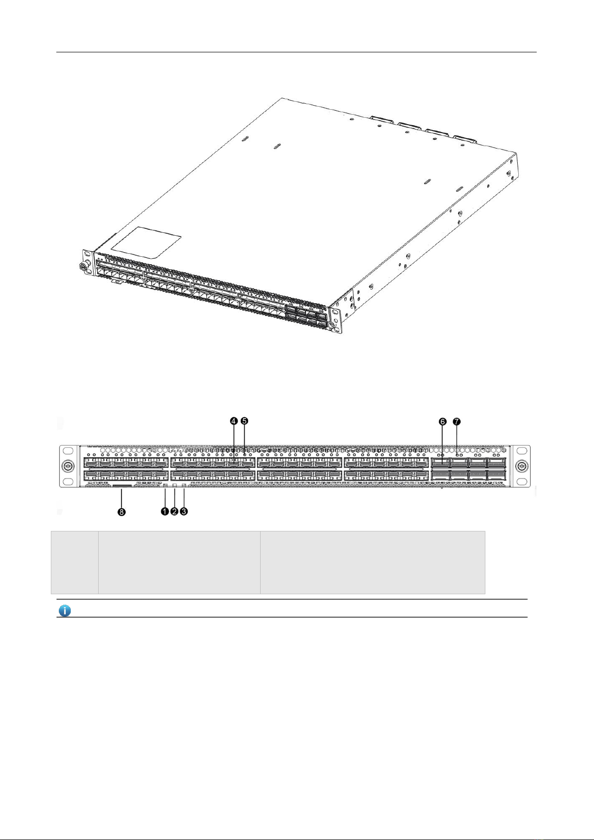
Figure 1- 1 Appearance of the M2-W6510-48V8C

Hardware Installation and Reference Guide Product Overview
- 5 -
Front Panel
Figure 1- 2 Front Panel of the W6510-48V8C
Notes:
1. Switch SYS status indicator
2. Power status indicator
3. Fan status indicator
4. SFP28 port
5. SFP28 port status indicator
6. QSFP28 port
7. QSFP28 port status indicator
8. Asset label
The M2-W6510-48V8C supports 100G QSFP28 module and 25G SFP28 module.
Back Panel
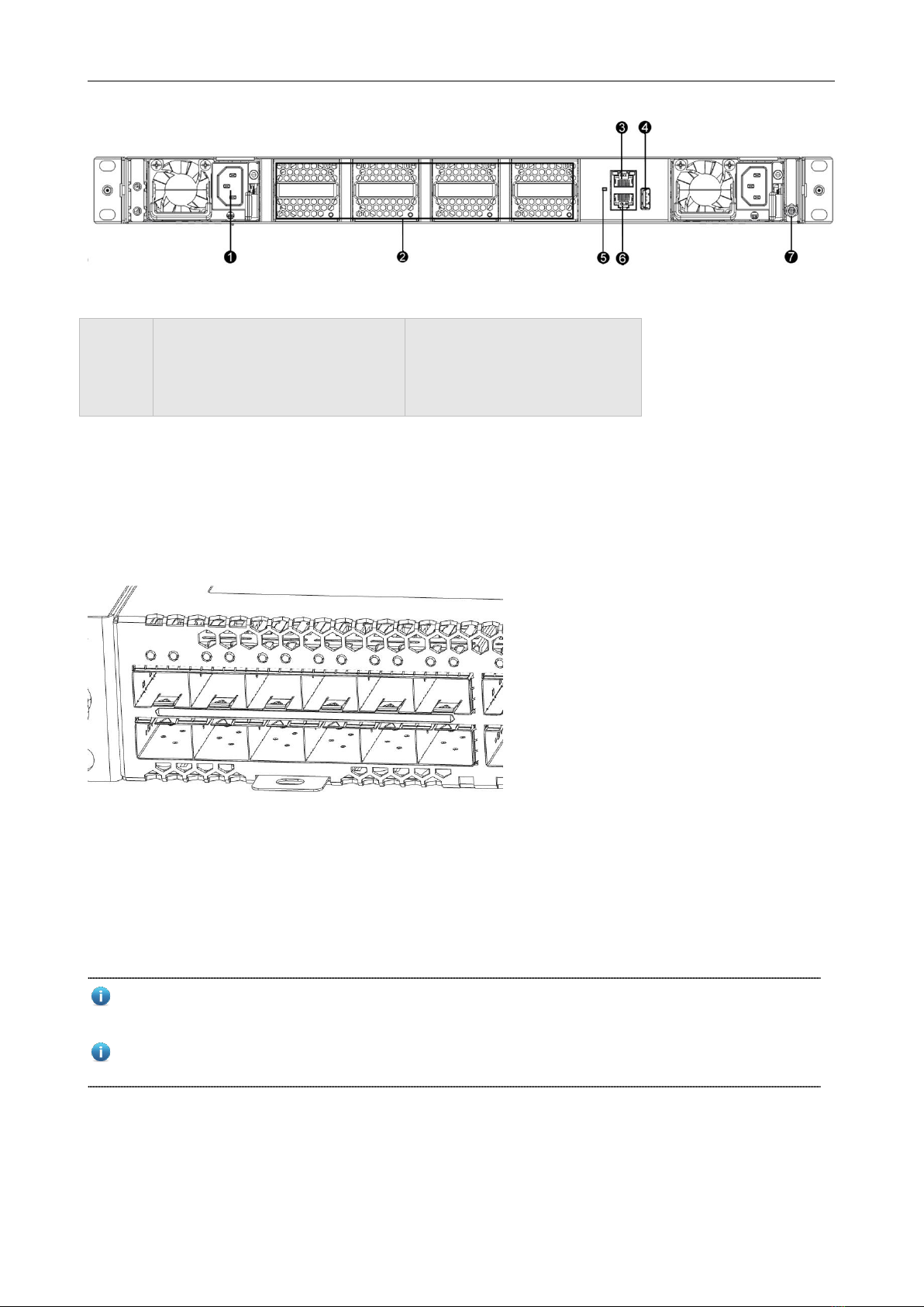
Figure 1- 3 Back Panel of the W6510-48V8C

Hardware Installation and Reference Guide Product Overview
- 6 -
Notes:
1. Power supply module slot
2. Fan module slot
3. MGMT port
4. USB 2.0 port
5. Switch status indicator
6. Console port
7. Grounding point
Asset Management Label
The asset management label is at the bottom of switch front panel. The label is movable and can be withdrawn from the
device. Users can mark the information such as asset name, category, code and registration date on the label which
helps to improve asset management accuracy and efficiency.
Figure 1- 4 Asset Management Label of the M2-W6510-48V8C
External Ports
The M2-W6510-48V8C provides the following ports:
Universal serial bus (USB) port: This port can connect with USB memory to save logs, host versions, warnings
and other diagnostic messages. Therefore, it is more convenient to upgrade the software version of the switch
online and save the log information.
To protect the data and avoid device damage, use qualified USB flash disks of good brands. At the same time, the
local USB port is compatible with most of the USB controllers except some USB flash disks.
The M2-W6510-48V8C switch supports debugging, configuration, maintenance, management and host software
uploading of Console ports.
Console port: Use RS-232 interface electrical level and standard RJ45 connector. This interface is connected with
the serial port of terminal PC to perform system debugging, configuration, maintenance, management, and host
software uploading.

Hardware Installation and Reference Guide Product Overview
- 7 -
MGMT port: This is an out-band Ethernet port, which uses standard RJ45 connector. This interface is connected
with Ethernet port of a PC to perform program downloading.
SFP28 port: There are 48 25G SFP28 ports, which support optical modules and DAC copper cables (10GBASE-X
compatible).
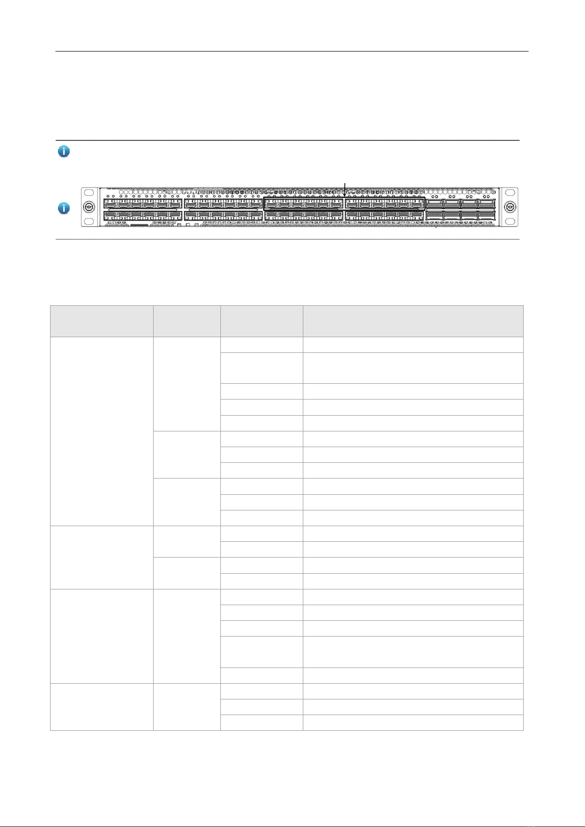
For better heat dissipation, the following 12 (6+6) SFP28 ports added port heat sink, will increase the strength of
inserting and pulling compared with other SFP28 ports.
QSFP28 port: There are 8 100G QSFP28 ports, which support optical modules and DAC copper cables. These

ports can also work in 4x25G mode.
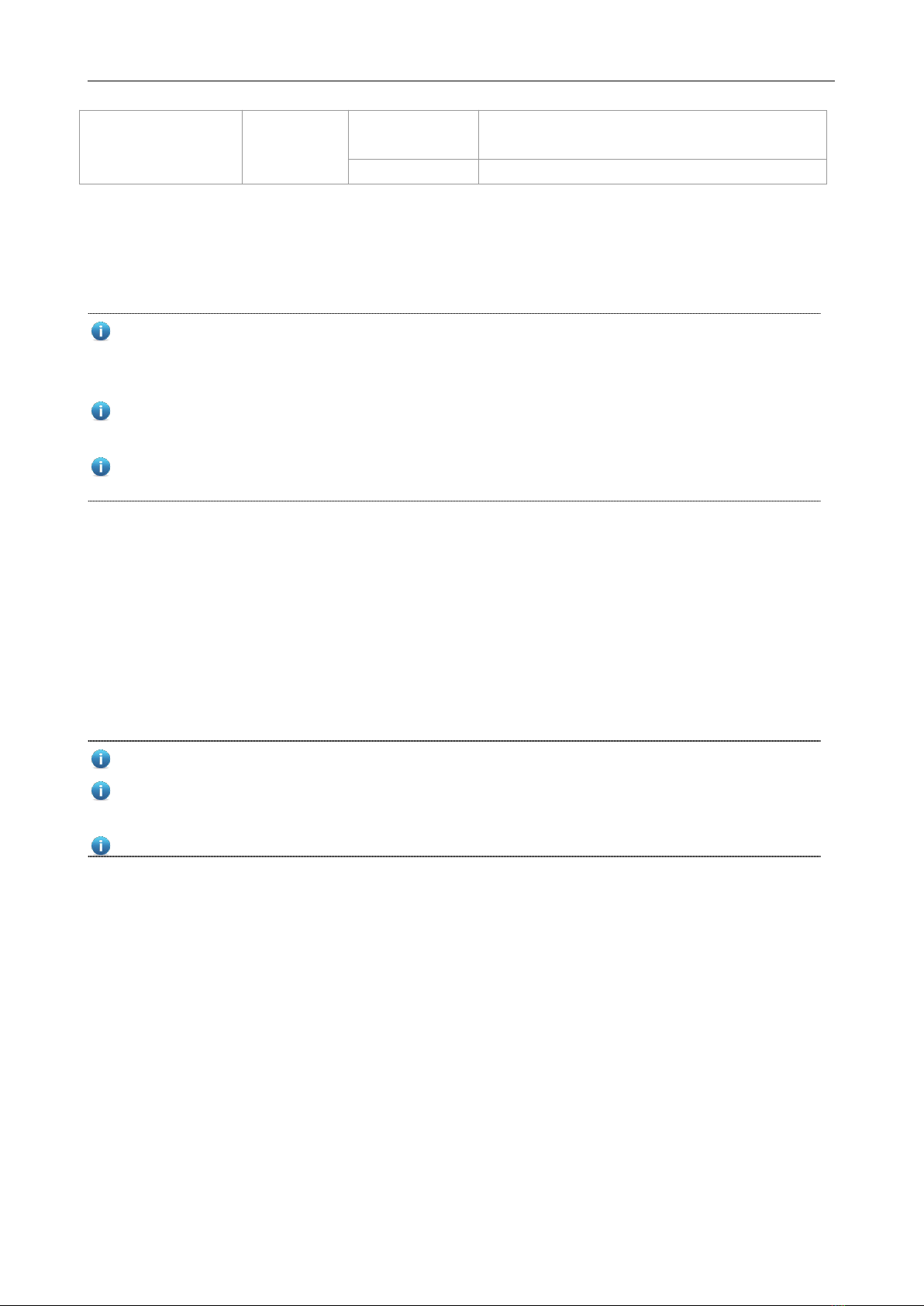
Indicator
Indicator
Panel
Identification
Status
Meaning
Switch status indicator
(Front panel/Back
panel)
SYS
Off
X86 system is not powered up.
Blinking green
(4Hz)
X86 system is initializing.
Solid green
X86 system works properly.
Solid yellow
X86 system warning occurs.
Solid red
X86 system have critical abnormality.
PSU
Solid green
Two PWR work properly.
Solid yellow
One PWR works abnormally.
Solid red
Two PWR work abnormally.
FAN
Solid green
FAN works properly.
Blinking green
One FAN works abnormally.
Solid red
More than one FANs work abnormally.
MGMT port status
indicator
LINK
Off
The port is not connected.
Solid green
The port is connected at 10M/100M/1000Mbps.
ACT
Off
The port is transmitting or receiving data.
Blinking
The port is transmitting or receiving data.
SFP28 port status
indicator
1F-48F
Off
The port is not connected.
Solid green
The port is connected at 25Gbps.
Blinking green
The port is transmitting or receiving data at 25Gbps.
Solid yellow
The system is initializing or the port is connected at
10Gbps.
Blinking yellow
The port is transmitting or receiving data at 10Gbps.
QSFP28 port status
indicator
49F-56F
Off
The port is not connected.
Solid green
The port is connected at 100Gbps.
Blinking green
The port is transmitting or receiving data at 100Gbps.

Hardware Installation and Reference Guide Product Overview
- 8 -
Solid yellow
The system is initializing or the port is connected at
40Gbps.
Blinking yellow
The port is transmitting or receiving data at 40Gbps.
Power Supply
The M2-W6510-48V8C switch supports power supply the PA550II-F/PA550II-R (according to air channel direction). The
smart power supply module supports power management, and the host can read input power, input current, and
temperature in real time. The power supply module supports hot swapping.
The M2-W6510-48V8C switch supports 1+1 power supply redundancy. To improve the stability and reliability of
the entire system, it is recommended to configure 1+1 power supply redundancy. When the two power supply
modules work normally, the switch is in the status of current sharing.
It requires at least one power supply module to work normally. Filler panels need to be installed in the unoccupied
power supply module slots to ensure ventilation and heat dissipation and avoid dusts.
Make sure the power modules air direction is same as fan modules. When the power modules are -F, the fan

modules should be -F as well.
Heat Dissipation
The working temperature of the M2-W6510-48V8C switch is 0°C to 45°C, or 32°F to 113°F, and the heat dissipation
design needs to ensure the stability, safety and maintainability in such environment. The M2-W6510-48V8C switch
adopts fan ventilation and forced convection to ensure the device can work normally in specified environment. Dust the
device every three months to avoid blocking the ventilation openings.
The M2-W6510-48V8C switch supports two air channel directions (PA550II-F for Port-to-PSU and PA550II-R for
PSU-to-Port) and provides fan speed regulation, fan failure warning, and fan hot swapping.
Leave sufficient space in the front and at the back of the chassis (at least 20 cm) for ventilation.
It requires at least three fan modules to work normally. Filler panels need to be installed in the unoccupied fan
module slots to ensure ventilation and heat dissipation and avoid dusts.
Power modules and fan modules with different air direction cannot be used together.
Inhaltsverzeichnis
Andere Micas Schalten Handbücher

Micas
Micas M2-W6930-64QC Installations- und Betriebsanleitung

Micas
Micas M2-S6920-4S Installations- und Betriebsanleitung

Micas
Micas RA-BM2-W6510-48V8C Installations- und Betriebsanleitung

Micas
Micas M2-W6010-48GT4X Installations- und Betriebsanleitung

Micas
Micas M2-S6510-32C Installations- und Betriebsanleitung

Micas
Micas M2-W6940-128QC Installations- und Betriebsanleitung

Micas
Micas M2-W6510-32C Installations- und Betriebsanleitung

Micas
Micas M2-W6910-64C Installations- und Betriebsanleitung

Micas
Micas M2-S6510-48V8C Installations- und Betriebsanleitung

Micas
Micas M2-S6930-64QC Installations- und Betriebsanleitung