
Midco Unipower G56B Kurzanleitung

Installation and Service Instructions
Midco® International Inc.
4140 West Victoria Street
Chicago, Illinois 60646
toll free 866.705.0514
tel 773.604.8700
fax 773.604.4070
web www.midcointernational.com
8470 86
• In the United States, installation must conform with local codes
or in the absence of local codes, with the National Fuel Gas
Code, ANSI Z223.1-latest edition available from American
National Standard Institute. Further reference should be made
to the recommendation of your fuel supplier.
• In Canada, installation must conform with local codes or in the
absence of local codes, with Installation Codes for Gas Burning
Appliances and Equipment, CGA Standard CAN/CGA 1-B-149.1
or 2.
• WARNING: Additions, changes, conversions
and service must be performed by an authorized Midco
representative, service agency or the fuel supplier. Use
only MIDCO specifi ed and approved parts.
• INSTALLER: Inform and demonstrate to the user the correct
operation and maintenance of the gas utilization equipment.
Inform the user of the hazards of storing fl ammable liquids
and vapors in the vicinity of this gas utilization equipment
and remove such hazards. Affi x this manual and associated
literature to the burner.
CODE COMPLIANCE IS THE SOLE
RESPONSIBILITY OF THE INSTALLER.
• USER: Retain this manual for future reference. If other than
routine service or maintenance as described in this manual
and associated literature is required, contact a qualifi ed service
agency. DO NOT ATTEMPT REPAIRS. An inadvertent service
error could result in a dangerous condition.
WARNING: If the information in these instructions
is not followed exactly, a fi re or explosion may result,
causing property damage, personal injury or death.
Do not store or use gasoline or other fl ammable vapors and
liquids in the vicinity of this or any other appliance.
WHAT TO DO IF YOU SMELL GAS:
• Do not try to light any appliance.
• Do not touch any electrical switch; do not use any
phone in your building.
• Immediately phone your gas supplier from another
building. Follow the gas supplier’s instructions. If
you cannot reach your gas supplier call the fi re
department.
Installation and service must be performed by a qualifi ed
installer, service agency or the gas supplier.
SAFETY INFORMATION TERMS: The following terms are used to identify hazards, safety precaution of special notations
and have standard meanings throughout this manual. They are printed in all capital letters using a bold type face as shown
below, and preceded by the exclamation mark symbol. When you see the safety alert symbol and one of the safety information
terms as shown below, be aware of the hazard potential.
DANGER: Identifi es the most serious hazards which will result in severe personal injury or death.
WARNING: Signifi es a hazard that could result in personal injury or death.
CAUTION: Identifi es unsafe practices which would result in minor personal injury or product and property
damage.
BURNER MODEL: ___________________________________
BILL OF MATERIAL
NUMBER: ___________________________________
SERIAL NUMBER #: ___________________________________
WIRING DIAGRAM: ___________________________________
FOR SERVICE CONTACT
Name: ____________________________________________
Address: ____________________________________________
____________________________________________
Phone: ____________________________________________
Date of Installation: ___________________________________
C
O
M
P
A
N
Y
R
E
G
I
S
T
E
R
E
D
AVOID ERROR IN PARTS SELECTION. When ordering use complete MIDCO
Part Number and Description. Furnish Burner Model Number, Bill of Material
Number and Serial Number (if available) from the specifi cation plate found on the
product.
IMPORTANT: Availability of parts as well as specifi cations are subject to change
without notice. Please consult factory for item availability.
MADE in the USA
Unipower
G56B G57B
G58B G69B
Gas Power Burners
414 ISO
U
L
®
2Midco International Inc. 8470 86
Specifi cations and Installation Instructions
Specifications SPECIFICATIONS
BURNER STYLE............................. Power Type
PILOT TYPE.................................... Intermittent, Spark Ignition
PILOT SAFETY............................... Instantaneous Electronic Flame Safeguard
STANDARD VOLTAGE
CONTROLS (FIELD WIRING) 120/1/60
MOTOR................................... 115/1/60 (except G69B-115/230/1/60)
U.L. LISTED
CAUTION: Unipower GB -Series are not intended for outdoor installation and must be
protected from excessive moisture. Provide adequate clearance for service and proper
operation.
Open basements will generally allow suffi cient air infi ltration, so special provisions will seldom be
required. If the heating plant is located in a separate furnace room or in an unusually tight basement,
permanent means must be provided to supply an ample volume of fresh air for combustion and
boiler room ventilation. A direct opening to the outside air should be provided sized on the basis of
1/2 square foot of free opening for each 1,000,000 BTU of burner rating when the vent connector is
equipped with a barometric draft control, 1 1/2 square feet when equipped with a draft hood. If the
ventilation opening is screened, it should be of 1-1/4″ mesh. The opening should be located at least
six feet over ground level to prevent accidental obstruction. If a direct opening to the outside air is
not available, an ample sized air duct can be run to the nearest outside air source; or, if practical,
open stairwells or building corridors connecting to an outside wall having a ventilating opening can be
used for this purpose, provided that no possibility of accidental closure exists.
While the spark ignition pilot system performs successfully under moderate or momentary back draft
conditions, it is not intended for operation under sustained reverse draft, for example in a building
with large ventilating fans but with insuffi cient make-up air. Even if burner operation is successful this
condition must be corrected to prevent the hazard of drawing fl ue gases into the building.
Consult your local gas company when doubt exists concerning boiler room ventilation.
_______________________________________
!
Part 1
Installation
I Ventilation
Model
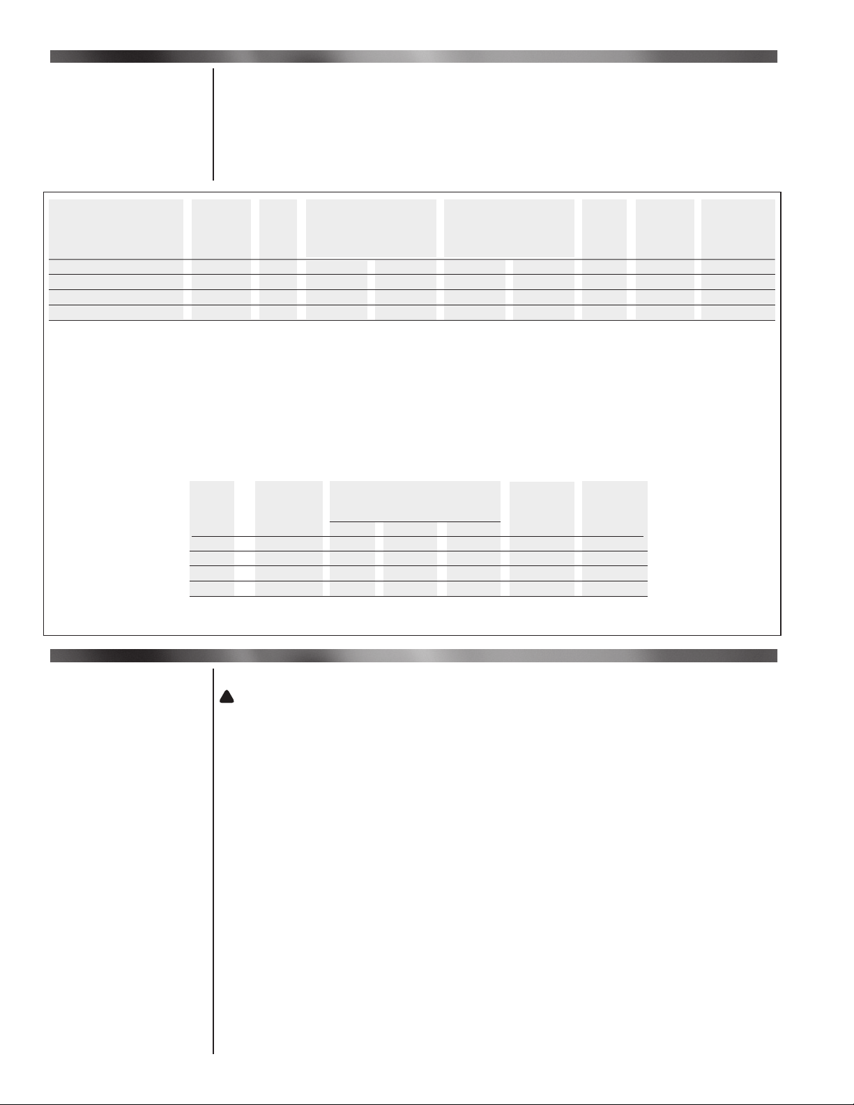
Natural Gas Propane Gas Max Input 1 Max Air Inlet Gas Pressure Burner Manifold Min Motor HP Recommended
(1,000 BTU/ (2,500 BTU/ MBTU/Hr. * SCFM 5 Required 2 Pressure 1,4,5 Input 3 (3450 RPM) Combustion
cu. ft.) cu. ft) Natural Propane Natural Propane MBTU/Hr. Chamber Sz
G56B G56BP 1075 224 5.0″ W.C. 5.0″ W.C. 2.2″ W.C. 1.2″ W.C. 300 1/6 42″ x 18″
G57B G57BP 1500 313 7.0″ W.C. 5.0″ W.C. 4.1″ W.C. 2.6″ W.C. 300 1/3 48″ x 21″
G58B G58BP 1800 385 6.7″ W.C. 6.0″ W.C. 4.6″ W.C. 3.8″ W.C. 500 1/2 50″ x 24″
G69B G69BP 2500 521 7.5″ W.C. 8.0″ W.C. 4.2″ W.C. 3.3″ W.C. 800 3/4 60″ x 27″
Table 1 - Burner Specifications
1. Values given based on +0.000″ W.C. fi rebox pressure, altitudes to 2000 feet. Derate burner for altitudes over 2000 feet by 4% for
each 1000 feet over sea level.
2. Maximum inlet pressure both gases: 14″ W.C. Refer to Section VI Piping for high pressure.
3. Modulating and two-step burners are limited to a 3 to 1 turndown ratio.
4. Manifold pressures are approximate and will vary slightly according to job condition. See Section VII para. 11.
5. Pressures are based on 25% excess combustion air.
6. SCFM = Standard Cubic Feet/Minute.
Min. Firing Maximum Capacity in MBH at Max Back Maximum
Model Rate Comb. Ch. - Back Pressure Pressure MBH * at
MBH * 0″ W.C. .25″ W.C. .5 ″ W.C. in ″ W.C. Max. B.P.
G56B 300 1075 950 875 0.7 700
G57B 300 1500 1400 1325 0.8 1325
G58B 500 1850 1750 1650 1.0 1400
G69B 800 2500 2375 2275 1.0 2100
* 1 MBH = 1,000 BTU/Hr
Table 2 - Maximum Capacity at Specified Back Pressures
Midco International Inc. 3
8470 86
Installation
The heating system, both the gas utilization equipment and the distribution system, should be in
good repair and suffi cient to properly heat the building. It should be determined if any serious faults
are present that would cause excessive fuel consumption, unsafe operation or improper heating,
and measures taken to correct them. After the grates and grate operating parts have been removed
from the fi rebox, the boiler interior should be thoroughly cleaned, removing all adhering dirt, tars,
scale and soot. All joints should be cemented to prevent excess air infi ltration into the boiler. Clean
out doors should be checked for close fi t, and sealed with furnace cement if they fi t poorly.
Firing door catches should be fi led off or otherwise arranged so that the door will open easily to
relieve pressure. No positive catches should be used. The use of a spring type door holder is
recommended.
_______________________________________
The UNIPOWER gas burner is designed for “in-shot” fi ring. It can be fi red into the ash pit of a boiler
designed for solid fuels, or it can be fi red into the primary heat exchanger of a boiler designed for
liquid or gaseous fuels. The ash pit installation requires a refractory lining. The combustion chamber
serves to contain and promote combustion and to protect non-heat exchange surfaces from direct
fl ame contact. Built-up combustion chambers should be made of 2600° insulting fi rebrick. As an
alternative, a monolithic fl oor can be cast in place, using a high temperature (2400°), light weight
insulating refractory. Check with your supplier to determine the thickness which will yield equivalent
insulating qualities. The top of the combustion chamber should be positioned 2 to 6″ above the
base of the heat exchanger. If the combustion chamber is to be set directly on the fl oor, provide
a minimum of 1/2″ insulating millboard or magnesia block underlay for fl oor protection. Use high
temperature fi ll such as vermiculite in voids around the combustion chamber. Any portion of the heat
exchanger not exposed to circulating air or water should be covered with insulating fi rebrick.
The combustion chamber sizes given in Table 1 are based on the maximum rated burner capacity.
If the input is to be permanently set at a reduced rate the combustion chamber fl oor area can be
reduced proportionately to the proposed input, with the length as closely proportioned to twice the
width as possible.
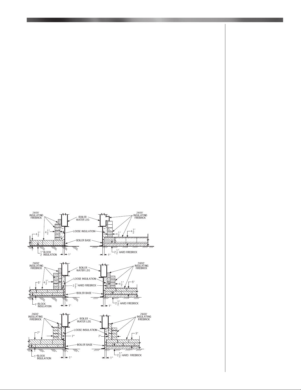
Where recommended size combustion chambers (225,000 BTU/sq. ft.) can be accommodated,
the type of construction shown in Figure 1 should be used. If lack of space prohibits use of this
construction, higher BTU values per square foot can be allowed for by using the constructions
shown in Figure 2 and 3.
II Gas Utilization
Equipment
III Combustion Chamber
Figure 1 - Typical Floor And Wall
Construction For 225,000 BTU Per
Square Foot. (Standard)
Figure 2 - Typical Floor And Wall
Construction For 275,000 BTU Per
Square Foot.
Figure 3 - Typical Floor And Wall
Construction For 350,000 BTU Per
Square Foot. (Maximum)
4Midco International Inc. 8470 86
Installation
The back wall of the combustion chamber should be carried 2 or 3 courses higher and overhung to
defl ect the fl ames from direct impingement on the rear heat exchanger surface. Hard fi rebrick should
be used to prevent erosion of the brick by high velocity gases.
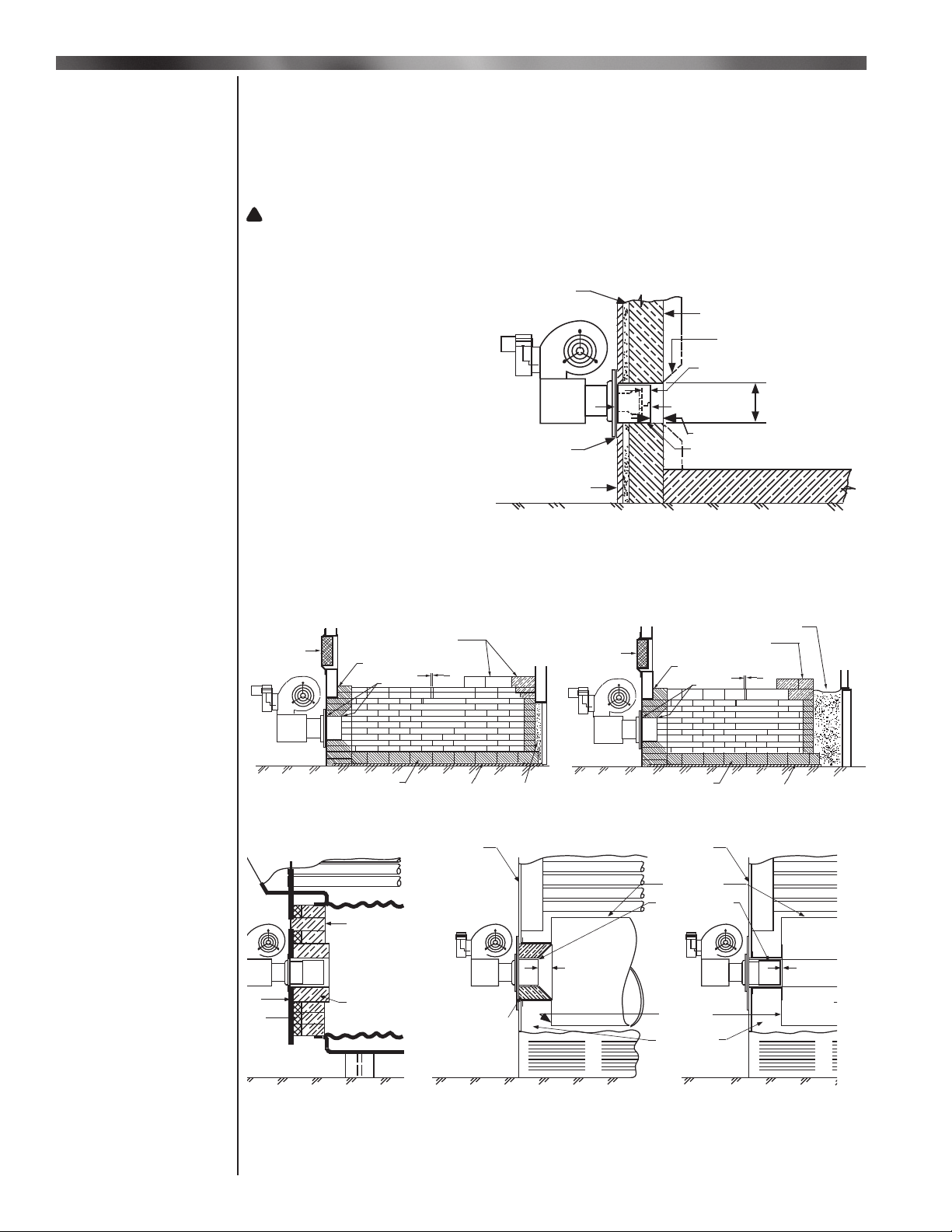
The burner is equipped with a mounting fl ange for direct attachment to the boiler front, and mounting
brackets forb legs. Use both if necessary for rigid installation. The burner nozzle must not extend
into the combustion chamber. It should be sealed into the opening as shown in Figure 4.
WARNING: BURNER CABINET MUST BE MOUNTED IN ORIENTATION IN FIGURES 4 AND
7. ANY OTHER MOUNTINGS MAY CAUSE A DANGEROUS CONDITION, AND WILL VOID
BURNER WARRANTY AND AGENCY APPROVALS. NON-STANDARD ARRANGEMENTS MAY
BE AVAILABLE FOR SOME MODELS-CONSULT FACTORY FOR DETAILS IF REQUIRED.
The refractory lined combustion
chamber can be omitted in “Scotch
Marine” and “Steam Generator” boilers
or warm air furnaces that include no
ash pits. The burner is fi red directly
into the heat changer, requiring no
refractory unless the combustion
chamber is so short that fl ame would
impinge excessively on the rear
heat exchanger wall (this particularly
important in a warm air furnace).
Refractory protection is recommended
if the length of the primary chamber is
less than 20% larger than the length
given in Table 1. In any case, the
burner entry wall must be refractory
lined if it is not a heat exchanger
surface.
!
BLOCK INSULATION
1/4" SOFT SHEET
GASKET OR ROPE
BOILER FRONT PLATE
*
* ADJUSTABLE NOZZLE SLEEVE LENGTH-5" TOTAL ADJUSTABLE NOZZLE
INSERTION DEPTH VARIABLE FROM 5" TO 10" TO ALLOW FOR THICKER
COMBUSTION CHAMBER WALL.
MIN. FRONT WALL
THICKNESS 4-3/4"
FLARE EXCESS WALL
THICKNESS 30¡-45¡
EXTEND SLEEVE BEYOND FLAME
RETENTION PLATE 1/2" MINIMUM
TUNNEL DIA.
G50Ñ6"
G60Ñ6-5/8"
SEAL WITH REFRACTORY CEMENT
0" TO 1-1/2"
Figure 4 - Construction at Burner Entrance
1"
4
INSULATE
DOOR
HARD FIREBRICK
ON REAR TOP ROWS
COVER WATER LEG BASE
SEAL
INSULATING
FIREBRICK
BLOCK
INSULATION
LOOSE
INSULATION
1"
4
INSULATE
DOOR
LOOSE INSULATION
HARD FIREBRICK
ON REAR TOP ROWS
COVER WATER LEG BASE
SEAL
INSULATING
FIREBRICK BLOCK
INSULATION
Figure 5 - Conventional Boiler - Small Firebox Figure 6 - Conventional Boiler - Large Firebox
FURNACE FRONT
FURNACE FRONT
COMBUSTION
CHAMBER
0" TO 3" 0" TO 3
FILLER SECTION WITH
REFRACTORY OR HIGH
TEMP, MINERAL WOOL
INSULATION
BURNER
DIA.
+ 2" MAX.
AIR COOLED
SURFACE
AIR PASSAGE
ADJUSTABLE
SLEEVE
LARGE DIAMETER BURNER ENTRY SMALL DIAMETER
BURNER ENTRY
WARM AIR FURNACES
LOOSE BRICK
FOR PEEPSIGHT
INSULATING
FIREBRICK
O
CK
A
TION
E
R
N
T
SCOTCH MARINE BOILER
Figure 7 - Tubular Combustion Chambers
III Combustion Chamber
Continued

Midco International Inc. 5
8470 86
Installation
Firing Door Installations
It is advantageous, on occasion, to fi re through the boiler fi ring door. For example, pitting can be
avoided on low base boilers, damage to the burner can be avoided if basement fl ooding is prevalent,
or the combustion chamber volume can be reduced in boilers with unusually large ash pits.
Great care in planning will be required for fi ring door applications since fl ame impingement on boiler
surfaces is more probable. Do not fi re a boiler which contains a drop section directly in the path of
the fl ame, or do not fi re over a water grate in a smokeless type boiler. The fi rebox length must be
great enough to exceed the combustion chamber lengths given in Table 1 by at least 20%.
When raising the fl oor, maintain suffi cient fi rebox volume to limit the heat release to 50,000 BTU per
hour per cubic foot or less. Use the entire fl oor as a combustion chamber and cover the water leg
base to 6″ from the bottom. Floor construction should conform to Figures 1 to 3.
Firing door installations will usually entail removal of the grates. Figure 8 shows a typical installation.
A steel plate fl oor can be supported from the grate lugs, if suitable. In any case, the fl oor must be
rigid enough to prevent sagging, being supported by brick piers as necessary. If fi ring over the grate,
level it off with rubble of common brick or fi rebrick if necessary; then cover over with insulating block
before laying the refractory fl oor.
The hearth of worm feed stokers can be used as a fl oor base. Level off the hearth to a suitable
height, remove the worm feed mechanism and fi ll the tuyere with rubble. Cover at least the tuyere
area with block insulation; if using castable refractory, pour a new fl oor over a leveling surface of
sand. The external stoker parts should be removed to eliminate clutter under the burner.
The burner mounting in the door must be rigid and refractory lined as shown in Figure 8. The burner
nozzle must not protrude directly into the combustion chamber. The refractory liner must extend
beyond or be fl ush with the burner face as shown in Figure 4. A sheet metal rim should encase
the refractory up to the inside of the boiler wall. It should be intermittently bent inward to retain the
refractory, or other means of anchoring should be provided.
As an alternate, the burner mounting plate can be extended externally to locate the nozzle face
and refractory wholly within the door opening. Seal carefully to prevent fl ue products from entering
the boiler room. In double door boilers it is recommended that the openings be enlarged to a single
opening by removing the center post so that the burner can fi re in the center. If a pressure part
of the boiler must be cut away, be sure to make modifi cations in accordance with your local code
covering boiler repairs.
Since fi ring door installations will generally leave no openings for fl ame observation, a peep sight
must be installed in the burner mounting plate.
_______________________________________
III Combustion Chamber
Continued
PEEP SIGHT
DOOR FRAME
PLASTIC OR
CASTABLE
REFRACTORY
INSULATING
FIREBRICK
1" 1"
HIGH TEMP MINERAL
WOOL SEAL
ANGLE IRON
FLOOR SUPPORT
STEEL
FLOOR
PLATE
BLOCK
INSULATION
STEEL
BURNER
MTG PLATE
BURNER
FLANGE
COMMON BRICK PIER
INSULATE DOOR
INTERMITTENT BENT LIP
FOR REFRACTORY ANCHOR
SEAL
COVER
WATERLEG BASE
LIGHT WEIGHT
INSULATING
CASTABLE
REFRACTORY
BLOCK
INSULATION
DRY SAND
DRY EARTH &
RUBBLE FILL
ASHPIT DOOR
OPENING
1" 1"
ALTERNATE
FLOOR CONSTRUCTION
SEAL ALL LOOSE
BOILER JOINTS
Figure 8 - Firing Door Installation in Three Pass Boiler

6Midco International Inc. 8470 86
Installation
WARNING: The chimney shall be inspected for unsafe conditions such as deteriorated
masonry and excessive soot or other blockage or potential blockage. Installation must
conform with local codes or in the absence of local codes with NFPA, ANSI Z223.1-latest
edition.
WARNING: No movable vent connector damper is permitted on any gas conversion
installation. The chimney should be inspected for unsafe conditions such as deteriorated
masonry and excessive soot or other blockage or potential blockage. Check your local
authorities for regulations covering barometric draft regulators on gas equipment.
WARNING: The vent connector shall not be connected to a chimney already venting solid
fuel burning equipment, an incinerator or an open fi re place.
The UNIPOWER burner does not depend on chimney draft. Combustion air is supplied by the forced
air blower, which is suffi cient to supply adequate air for any normal boiler. This reduces the function
of the chimney to removal of fl ue products from the boiler. A chimney height of 15′ above the boiler
fl ue outlet will generally prove ample if the recommended, or larger, vent connector and chimney
diameters are used. The chimney must of course extend several feet over the roof of the building,
or adjacent buildings. Vent connector material should be 24 gauge or heavier steel, galvanized to
resist corrosion. The horizontal run of vent connector should be pitched upward from the appliance
fl ue outlet at least 1/4″ to the foot. Avoid excess elbows or other constructional features that would
create excessive resistance to fl ow of fl ue products. Fasten joints with sheet metal screws to prevent
sagging. The vent connector should be maintained at least 6″ from combustible building materials;
more if it is uninsulated. Where it passes through partitions constructed of combustible materials a
ventilated thimble should be used. Refer to your local building codes. The vent connector should be
fi rmly cemented into the chimney but must not extend beyond the inner face. Where two or more
appliances use the same chimney, be sure not to enter the chimney with both fl ue pipes at the same
level.
Do not arbitrarily reduce the vent connector size, since a boiler back pressure can build up, leading
to possible leakage of fl ue products into the boiler room.
Chimney construction can be either of brick, preferably tile lined, or of steel. Joints in the chimney
should be smooth and leak free to prevent uncontrollable air infi ltration. They should be made so
that condensation, if any, will not collect in the joints or leak to the outside.
If the vent connector must be extra long, the area of the pipe and chimney should be increased,
or the chimney height must be increased, or both. Never allow the horizontal length of the vent
connector to exceed the height of the chimney.
Two kinds of draft control are acceptable; an A.G.A. type draft hood as illustrated in Figure 9, or
a barometric damper as shown in Figure 10. Use of a draft hood is usually limited to burners with
lower range capacities, while a barometric draft control is suitable for all capacities. Application
should depend on the requirements of the installation.
!
IV Chimney, Vent
Connector and Draft
Control
!
!
CORRECT LOCATIONS
INCORRECT LOCATIONS
Figure 9 - Draft Hoods
Figure 10 - Barometric Damper
Figure 9 and 10: Copyright by the American Gas
Association. Used by permission of the copyright holder.
Midco International Inc. 7
8470 86
Installation
If a draft hood is used, it should be of the same size as the vent connector and should be located
higher than the highest part of the heating appliance fl ue passage.
If a barometric damper is used, it should be of the double-swing type, which opens freely outward to
aff ord downdraft protection irrespective of settings made to the balancing weights for updraft control.
The damper should be located so it is free to swing without interference from surrounding objects so
that the velocity pressure of the fl ue gases does not interfere with its operation. See Figure 10 for
proper installation.
When any vent connector passes through a partition the draft control must be located in the same
room as the heating appliance. A device which will automatically shut off gas to the burner in the
event of sustained backdraft is recommended if such backdraft might adversely aff ect burner
operation or if fl ue gas spillage might introduce a hazard. If such a device is used, it shall be of
the listed type and installed and adjusted by a qualifi ed service technician in accordance with the
manufacturer’s instructions.
_______________________________________
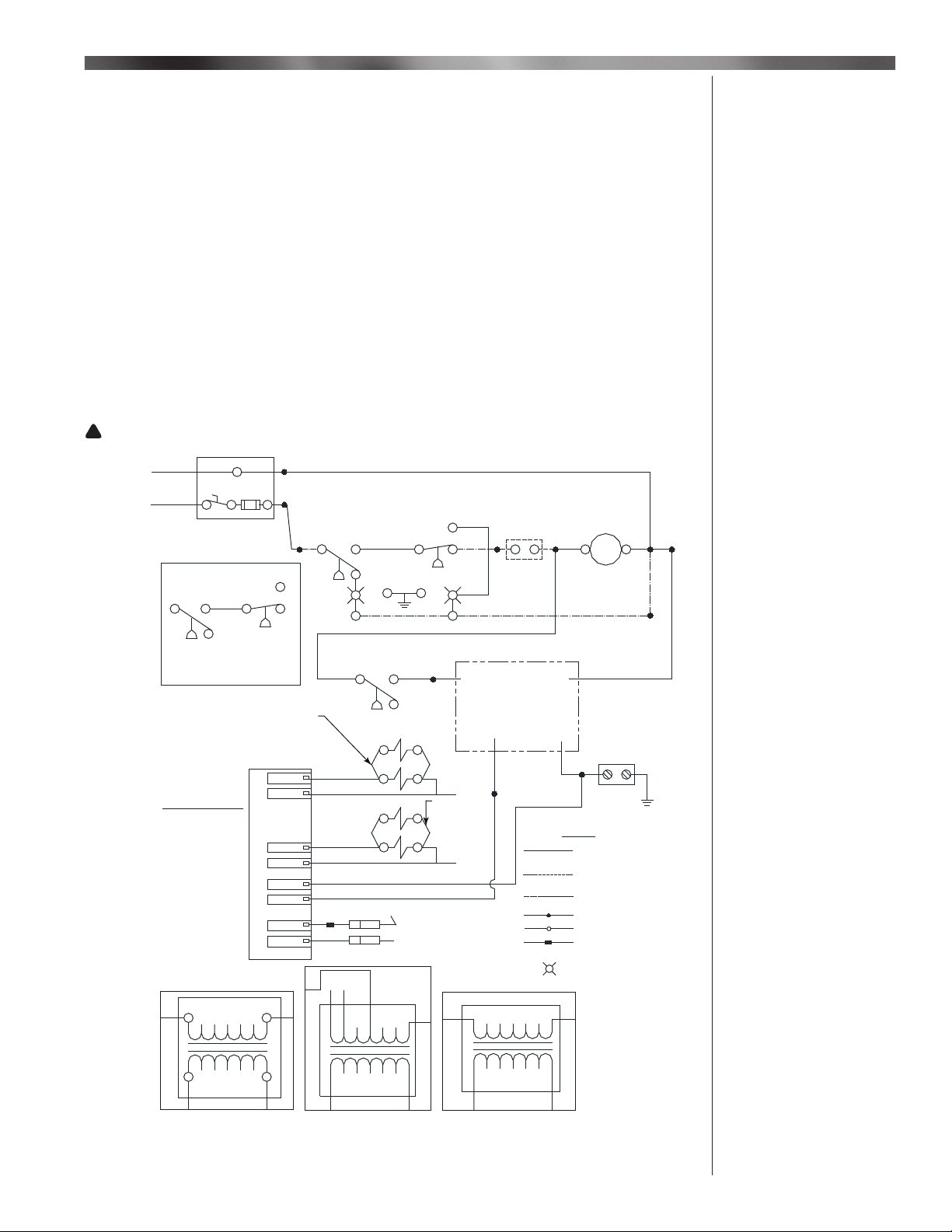
The burner, when installed, must be wired and grounded in accordance with local codes, or, in the
absence of local codes, with the National Electric Code ANSI/NFPA No. 70-latest edition. In Canada,
refer to CSA Standard C22.1, “Canadian Electrical Code Part 1.”
CAUTION: REFER TO THE SEPARATE WIRING DIAGRAM INCLUDED WITH EACH
BURNER.
V Electrical
!
NEUTRAL
PILOT GAS VALVE
SENSE ROD
SPARK ROD
Y
BEFORE DATE CODE 4 0 9 7
HI-LO GAS SWITCH WIRING
3(NC)
2(NO)
1(C)
5(NO)
4(C)
6(NC)
R (BK)
BR
BL/W
R (BK)
BL
W
BK
SPARK
SENSE
24V
24V GND
GND
PV
MV/PV
MV
S8680J
ELECTRONIC
CONTROL
HOT
OPTIONAL HI-LO GAS
PRESSURE SWITCH IF NOT USED
JUMPER 6 TO 7
10
120/1/60
9
3
876
2(NO)
GG
1(NC)3(C)
2(NO)
2(NO)
(1)NC
AIR SWITCH
BLOWER
(2)NO
1(C)
(3)NC
115V
BLOWER
MOTOR
Y
L2
L1
W
BK
R
R
W
Y/BK
R
BL
YG
OPT.
REDUNDANT
PILOT VALVE
MAIN GAS VALVE
AND REDUNDANT
VALVE
SEE DETAILS
A, B & C
L2
L2
SAFETY &
OPERATING
CONTROLS
BL
BK
BR
O
R
W
P
Y
G
/BK
/W
NU
PGT
BL BLUE
BK BLACK
BROWN
ORANGE
RED
WHITE
PURPLE
YELLOW
GREEN
BLACK STRIPE
WHITE STRIPE
NOT USED
PIG TAIL
ABBREVIATIONS
5BURNER STRIP
COMPONENT
LIGHT
(LOCATED IN GAS SWITCH
ENCLOSURE)
SPLICE CONNECTION
OPTIONAL WIRING AND
COMPONENTS BY MIDCO
WIRING AND
COMPONENTS BY INSTALLER
WIRING AND
COMPONENTS BY MIDCO
LEGEND:
Y
24V
C
120V
BL
W
Y/
BK
8447-27
W
BL
C
24V
Y
120V
BK
R
O
208V NU
NU
240V
8447-31
DETAIL A DETAIL B DETAIL C
BK W
BL
120V C
24V
Y
8447-32
Figure 11 - Wiring
IV Chimney, Vent
Connector and Draft
Control
8Midco International Inc. 8470 86
Installation
When wiring, be sure that the electric power take-off is connected to a permanently live circuit and
use multiple 14 gage copper wire conductors. Provide a fused disconnect switch in the burner
circuit. Each installation must include a limit control to guard against excess temperature or steam
pressure. Steam or vapor systems will require a low water cut-off .
_______________________________________
For the usual low pressure gas supply system, 5″ to 14″ W.C. NATURAL (11″ to 14″ W.C. Propane)
use Table 3 to fi nd the recommended gas supply line size.
Piping follows normal practices and should be connected to the burner in the manner shown in
Figure 12. If the piping must be rearranged because of space limitations be sure to carry out the
sequence of components illustrated. While the pilot regulator can be mounted in any position, the
main regulator should be mounted upright and in a horizontal run of pipe.
Run full size pipe or tubing from regulator vent openings to outside of building. Provide no traps in
the vent lines and terminate away from all doors and windows; also make provisions for keeping rain
and foreign objects from entering the vent piping.
When high supply gas pressure is encountered, as in the case in many industrial plants, the gas
line size can be reduced to allow for a greater pressure drop; however, the size must be suffi cient to
delivery burner rating pressure.
CAUTION: High gas pressure supply lines require the proper pressure reducing
regulators. Install two separate high pressure regulators, of the Tight Shut-Off type upstream
of the low pressure regulators. One sized for main gas input, and one suitable for the
minimum fl ow regulating capacity of the pilot.
The high pressure regulators may be substituted for the low pressure regulators. If high pressure
regulators are used as substitutes, they must be adjustable down to a minimum of 2″ W.C. outlet
pressure for the pilot and 5″ W.C. for the main gas. They must be adjustable down to the maximum
burner inlet pressure rating (14″ W.C.).
DANGER: Explosion hazard.
Do not use oxygen for pressure testing. An explosion could occur during initial start-up.
When the gas supply line is about to be put into service it must be tested to insure that it is gas tight.
Use air or inert gas under pressure and test with soap and water or other liquids to locate leaks.
CAUTION: Because it is diffi cult to accurately control pressure, disconnect all low
pressure (14″W.C. max.) components (main and pilot) during supply pipe leak testing.
Exposing low pressure regulators and valves to a pressure over 1Ú2 PSIG (14″W.C.) will
damage components and void their warranties.
Gas Supply Type of Approximate Capacity - MBH
Pipe Size Gas Length of Pipe - Feet
N.P.T. 20 40 60 100 200
1″ Natural 350
Propane 550 385 300
1 - 1/4″ Natural 730 500 400 300
Propane 1150 785 630 480 330
1 - 1/2″ Natural 1100 760 610 460 320
Propane 1730 1200 960 725 500
2″ Natural 2100 1450 1150 870 610
Propane 2500 2280 1800 1370 960
2 - 1/2″ Natural 2500 2300 1850 1400 980
Propane 2500 2500 2200 1550
3″ Natural 2500 2500 2500 1700
Propane 2500 2500
CAUTION: Do not exceed maximum rated capacity of burner model -
See Tables 1 and 2
Capacities shown are for total pressure drop of .3″ W.C. For higher permissible
pressure drops consult your fuel supplier.
Source: Gas Engineers Handbook - 1974
Table 3 Schedule 40 Pipe Capacity Chart
V Electrical
Continued
VI Piping
!
!
!
!

Midco International Inc. 9
8470 86
Installation
Before gas is introduced to the system, a check must be made to see that there are no open fi ttings
and to make sure the burner main and pilot manual valves are closed. After checking above, purge
the gas line up to the burner inlet. Purging the air from the gas supply line at this step will expedite
the fi rst light-off .
CAUTION: Purge outside the building. Do not purge into the gas utilization equipment
combustion chamber.
_______________________________________
WARNING: Repeated unsuccessful attempts to light may result in accumulated gases in
gas utilization equipment and chimney. To prevent these gases from reaching an explosive
level, periodically purge the gas utilization equipment.
CAUTION: All cover plates, guards, and enclosures must be maintained in place at all
times except during maintenance and servicing.
CAUTION: Optional equipment and/or special limit controls such as high/low gas
pressure switches can alter the start-up procedure. See Section XIV SPECIAL EQUIPMENT.
Special Equipment
1. Check the piping for leaks. A quick way to do this is to close the main manual shut-off valve and
manual pilot valve, then turn on the gas pressure to the gas supply line and observe the meter
test dial. There should be no movement of the test dial hand for at least twenty minutes. All other
gas appliances must be completely shut off during this test (including pilots). If a leak is detected it
should be located with a soap suds test. Test the main automatic valve for tightness. (see Section
XII for instructions). The ball valve is intended to be open at all times except when testing for main
valve leakage. The Main Manual Shut-Off Valve must be used for manual gas shut-off .
2. Make sure that the burner main and pilot gas lines are completely purged of air. Do not purge into
the combustion chamber. Purge outside the building.
3. Make sure the burner power switch is off , manual valve is closed, pilot manual valve is closed,
motor is free to rotate, and fl ame safeguard reset button is set.
4. Make the proper settings on all limit controls and set controller to call for heat.
5. Set blower air shutter wide open.
VI Piping
Continued
!
MAIN REGULATOR
MAIN REGULATOR
VENT
PILOT MANUAL VALVE
BALL
VALVE
PILOT
REGULATOR
BLOWER
MOTOR
MANUAL MOTOR RESET
BUTTON
(MAY HAVE AUTO RESET)
MANIFOLD PRESSURE
TAP
DRIP LEG
REDUNDANT MAIN AUTOMATIC VALVES BF INPUT ADJUSTER
(HIDDEN)
BALL VALVE
PILOT
SOLENOID
VALVE
PILOT MIXING
TEE
PILOT
PRESSURE TAP
PEEP SIGHT
PILOT AIR
TUBE
BLOWER
AIR
SWITCH
INLET PRESSURE TAP
1/4 TEE 1/4 PLUG
Figure 12 - Piping Connections
VII Initial Start-UP
!
!
!
10 Midco International Inc. 8470 86
Installation
6. Turn on the line switch, and allow motor to run through the pre-purge and ignition cycle. Check
the blower wheel for proper rotation. Viewing from the motor shaft end (Blower Inlet side), rotation
should be counter clockwise. After a short run, the fl ame safeguard will lock out, stopping the motor.
Wait one minute, then reset the fl ame safeguard.
7. Turn on pilot manual valve. With Main Manual Shut-Off Valve still closed, turn on main line switch.
Motor will start. When pre-purge period has elapsed, fl ame safeguard will energize pilot solenoid
valve and spark generator. When fl amerod senses pilot fl ame, the fl ame safeguard will energize the
main valves. No main fl ame will occur due to closed Main Manual Shut-Off Valve. Quickly observe
pilot fl ame . If no fl ame, or if weak, screw in pilot regulator adjustment. If the fl ame is rich and fl oating
from the pilot tip, back off the pilot regulator. Set to achieve the largest stable blue fl ame with a base
that burns fi rmly within the pilot tip. The best operating pressure is usually 3-1/2″ to 4″ W.C.. Test for
ignition and stability several times, cycling the burner with both open and closed air shutter. Ignition
and relay response will be prompt with a good fl ame. Check fl ame signal with a AC micrometer.
Pilot should be set to yield the highest steady reading, at least 2 microamps AC and as high as 5
microamps.
8. Check operation of the electronic fl ame detection circuit by turning off the pilot manual valve with
pilot burning and main manual shut-off valve still closed. The circuit to the main automatic valve
should be broken when the pilot goes out.
*9. Turn off line switch to stop the burner. Reset fl ame safeguard. Set blower air shutter about 1/4
open. Loosen gland nut on Butterfl y Valve and temporarily lock air shutter wide open (slot in shaft
parallel to fl ow).
10. Turn on main line switch. After the main valve is energized, slowly open main manual shut-off
valve until the main fl ame ignites. Then, opening the air shutter as required to maintain a suitable
fl ame, slowly open the main manual shut-off valve to the wide open position or until, with the air
shutter wide open, the main fl ame becomes excessively rich.
*11. The manifold pressures shown in tables 1 and 5 may be used to determine the approximate
gas input settings. The gas input for Natural gas models can be determined by timing the gas meter.
Accurately time test dial for the number of seconds for one revolution and use the following formula.
All other gas utilization equipment must be off .
3600 x test dial size x BTU value = BTU / Hr.
no. of seconds for one rev. test dial
Then divide by 1,000 for MBH value.
Example 3600 x 1 x 1000 = 720,000 BTU / Hr. = 720 MBH
5
For Propane gas, consult your supplier for method of determining fi ring rate.
CAUTION: The manifold pressures shown in tables are both the blower air pressure and
the gas pressure. Air shutter adjustments will eff ect manifold pressure and input.
Clock the meter gas rate and (if necessary) reset the main regulator to control gas fl ow at about 10%
over burner rating or over desired input with Main Manual Shut-Off Valve wide open. Turning the
adjustment screw clockwise on main regulator increases pressure and fl ow rate, reverse decreases.
Do not adjust the regulator past the point where no further change in gas fl ow is noted. “Close” off
Butterfl y Valve to the desired maximum input rate, secure gland nut, and replace cap. Reset the
blower air shutter to provide fairly long fl ame, blue at the burner face, orange or red at the tips.
Flashes of yellow may be visible. Close fi ring door for a few seconds; then open and quickly observe
fi re. If a purple haze is noted at the rear of the fi rebox, lack of air is indicated and air shutter should
be opened wider.
Refer to Table 4 if the manifold pressure is to be used as a guide to gas input.
12. Check the fl ue gas temperature at the boiler fl ue outlet. It should be above 325° but not
exceeding 550°. Excessive fl ue temperatures result in low effi ciencies. Low fl ue gas temperatures
may cause excessive condensation. Reset input if necessary to adjust stack temperature; or if
temperature is too low, portions of the heat exchanger surface can be blocked off with insulating
fi rebrick.
VII Initial Start-UP
Continued
!
Dieses Handbuch passt für folgende Modelle
7
Inhaltsverzeichnis
Andere Midco Kamin im Innenbereich Handbücher


