Mikster INDU WRC-2010H Bedienungsanleitung

ver. 1.07
INDU WRC-2010H Controller
User’s Manual
Sp. z o.o.
41-250 Czeladź, ul. Wojkowicka 21
Tel. 0 32 763–77–77
Fax: 0 32 763–75–94
www.mikster.pl e-mail: [email protected]
v1.07 29.05.2008

INDU WRC-2010H Controller – User’s Manual ver. 1.07
- 2-
29.05.2008
TABLE OF CONTENTS
page
1.
STRUCTURE,
APPLICATIONS,
POTENTIAL.....................................................................................................4
2.
“INDU
WRC-2010H”
-
CONTROL
PANEL............................................................................................................4
3.
“INDU
WRC-2010H”
-
START
OF
OPERATION..................................................................................................6
4.
PROCESS
PROGRAMS......................................................................................................................................6
4.1. Manufacturing process programming............................................................................................................6
4.2. Execution of program stored in memory .......................................................................................................8
4.3. Program execution interruption .....................................................................................................................9
4.4. Automatic process activation.........................................................................................................................9
4.5. Editing of parameters set during controller operation..................................................................................11
5.
CONTROLLER
CONFIGURATION....................................................................................................................12
5.1. User’s functions...........................................................................................................................................13
5.1.1. Time and date setting ...........................................................................................................................13
5.1.2. Setting menu language.........................................................................................................................13
5.2. Service functions 1......................................................................................................................................15
5.2.1. Controller parameter setting .................................................................................................................15
5.2.2. Setting of step parameters....................................................................................................................20
5.2.3. Alarm setting.........................................................................................................................................22
5.2.4. Parameter setting for pause mode, stop mode and key functions F1..F4............................................26
5.2.5. I/O output parameter setting.................................................................................................................27
5.2.6. Washing parameter setting...................................................................................................................31
5.3. Service functions 2......................................................................................................................................31
5.3.1. Test for digital outputs...........................................................................................................................31
5.3.2. Key test.................................................................................................................................................32
5.3.3. Diode test..............................................................................................................................................32
5.4. Washing ......................................................................................................................................................33
5.4.1. Washing programming .........................................................................................................................33
5.4.2. Washing activation................................................................................................................................33
6.
ADDITIONAL
INFORMATION............................................................................................................................34
6.1. Display of additional measurements............................................................................................................34
7.
HOW
TO
CONNECT
THE
CONTROLLER
TO
PC
COMPUTER.......................................................................34
8.
TECHNICAL
DATA.............................................................................................................................................35
II
INDU
WRC
CPU-01
MODULE............................................................................................................................36
1.
MODULE
ASSEMBLING....................................................................................................................................36
2.
MODULE
FUNCTION.........................................................................................................................................36
3.
FIGURE..............................................................................................................................................................36
4.
TECHNICAL
DATA.............................................................................................................................................37
III.
INDU
WRC
AI-01/6
MODULE ...........................................................................................................................38
1.
MODULE
ASSEMBLING....................................................................................................................................38
2.
MODULE
FUNCTION.........................................................................................................................................38
3.
FIGURE..............................................................................................................................................................38
4.
TECHNICAL
DATA.............................................................................................................................................39
IV.
INDU
WRC
DI-01MODULE..............................................................................................................................40
1.
MODULE
ASSEMBLING....................................................................................................................................40
2.
MODULE
FUNCTIONS......................................................................................................................................40
3.
FIGURE..............................................................................................................................................................40
4.
TECHNICAL
DATA.............................................................................................................................................41

INDU WRC-2010H Controller – User’s Manual ver. 1.07
- 3-
29.05.2008
V.
INDU
WRC
RO-01
MODULE............................................................................................................................42
1.
MODULE
ASSEMBLING....................................................................................................................................42
2.
MODULE
FUNCTIONS......................................................................................................................................42
3.FIGURE...............................................................................................................................................................42
4.
TECHNICAL
DATA.............................................................................................................................................43
5.
C
ARDS ADDRESSING IN THE SYSTEM
:.....................................................................................................................43
VI.
INDU
WRC
TO-01
MODULE............................................................................................................................44
1.
MODULE
ASSEMBLING....................................................................................................................................44
2.
MODULE
FUNCTION.........................................................................................................................................44
3.
FIGURE..............................................................................................................................................................44
4.
TECHNICAL
DATA.............................................................................................................................................45
5.
C
ARDS ADDRESSING IN THE SYSTEM
:.....................................................................................................................45
VII.
INDU
WRC
COM-01
MODULE........................................................................................................................46
1.
MODULE
ASSEMBLING....................................................................................................................................46
2.
MODULE
FUNCTION.........................................................................................................................................46
3.
FIGURE..............................................................................................................................................................46
4.
TECHNICAL
DATA.............................................................................................................................................47
VIII.
INDU
WRC
PS-01
MODULE...........................................................................................................................48
1.
MODULE
ASSEMBLING....................................................................................................................................48
2.
MODULE
FUNCTION.........................................................................................................................................48
3.FIGURE...............................................................................................................................................................48
4.
TECHNICAL
DATA.............................................................................................................................................49

INDU WRC-2010H Controller – User’s Manual ver. 1.07
- 4-
29.05.2008
1. STRUCTURE, APPLICATIONS, POTENTIAL
The INDU WRC-2010H Controller is a unit designed to control those industrial processes, in which temperature is
the most important element, such as: smoke-chambers, brewing boilers, defrosting chambers, etc. Smoke-
chamber control is the main purpose, for which this controller has been built, and this is reflected in the type of data
being shown, controller operation procedure, etc. The controller consists of modules - users may fit their number
and type to their own needs. The main module is the “Control Panel”, indispensable in any controller, which allows
to:
-configure the whole controller
-set parameters controlling the process
-observe current measurements
Other modules, which may be added to the controller (in brackets: maximum number of modules of a given type):
-analog input module (2 modules – 12 input lines) – temperature measurements using the PT100
-digital input module (1 module – 11 input lines) – inputs signaling alarm, or additional external control signals
-relay output modules (6 modules – 32 output lines [1 module has 6 lines]) - relays to control executive
equipment
-communication module (1 module) – allows to communicate with the PC computer, and stores recordings of
process course parameters
-power supply module (1 module) – the controller power supply – indispensable
Modules may be put together in any configuration.
2. “INDU WRC-2010H” - CONTROL PANEL
All operations related to the controller activation, programming, etc., are executed through the control panel.
Keys on the control panel are arranged in the following keypads:
-numeric display keypad (1) – displays process preset parameters [green], and current measurements [red]
-graphic display (2) - displays all information related to the panel configuration and operation
-NUMERIC keys with FUNCTION keys (3) – allow to operate the controller
-diodes signaling OUTPUT EQUIPMENT STATUS (4) – show status of output relays
Process control is divided into stages referred to as process cycles, each process may consist of 30 cycles, and
each cycle is characterized by:
-currently executed process step
-preset chamber temperature
-preset bar temperature
-preset humidity
-preset cycle duration time
Process step is the information stored in the controller stating which outputs are to be active, and what is the
condition for particular cycle termination. 16 process steps may be stored in the INDU WRC-2010H memory.
Information regarding status of working controller, as process number and name, or process step number and
name, is shown on graphic display.

INDU WRC-2010H Controller – User’s Manual ver. 1.07
- 5-
29.05.2008
Fig. 1
The INDU WRC-2010H Controller “control panel”
1. Numeric
display keypad
2. Graphic
display
3. Numeric keys
with function
keys
4. Signaling
diodes

INDU WRC-2010H Controller – User’s Manual ver. 1.07
- 6-
29.05.2008
3. “INDU WRC-2010H” - START OF OPERATION
As soon as power is turned on, all numeric displays and diodes will light, and graphic display will show “WRC 2000
Init”. After some time displays and diodes will be switched off, which proves correct work of the system. The
controller will switch to stand-by mode. Graphic display will show request to enter operator’s number, and then
password. Before operators are entered, it is enough to press “Enter” key twice.
4. PROCESS PROGRAMS
4.1. Manufacturing process programming
Do the following in order to create a new program or edit an already existing one:
-press the “Configuration” key
-using arrows “left” - “right”, position the cursor so as to make the figure blink and to have the word
“Programowanie” [“Programming”] displayed
press the “Enter” key
-password will be requested
******
enter the code “003011” and press “Enter”
-program selection list will be displayed
-using arrows “up” - “down”, select the program you wish to enter or modify
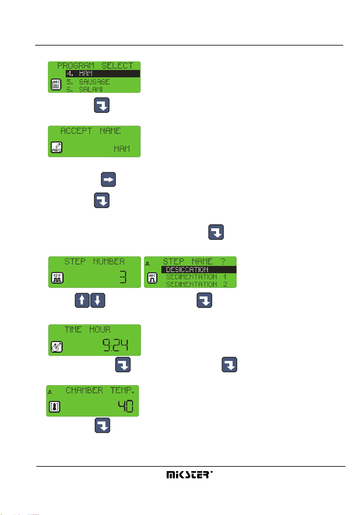
INDU WRC-2010H Controller – User’s Manual ver. 1.07
- 7-
29.05.2008
-selected program blinks
-press “Enter” key to edit the program
-first enter program name
(enter letter in position by pressing key with selected letter as many times as required, move to next position by
pressing right arrow )
-press “Enter” key
-start process cycle editing
-enter the number of cycle you wish to edit and press “Enter”
-select step number to be executed during the cycle
1
(using arrows “up” - “down”), and press “Enter”
-enter the cycle duration,
first hours, press “Enter” , then minutes, and press “Enter” again
-enter preset chamber temperature
1
and press “Enter”

INDU WRC-2010H Controller – User’s Manual ver. 1.07
- 8-
29.05.2008
-enter preset bar temperature
1
and press “Enter”
-enter preset humidity
1
and press “Enter”
-shift between data you are entering with arrows
-this ends editing of a single process; if you wish to edit another cycle, enter its number and then proceed as
before, whereas if all cycles in a given program have been edited, then press “Stop” key
-thus you have completed program editing, now you can select another program for editing, or:
-press “Stop” key and thus end manufacturing process programming
4.2. Execution of program stored in memory
Do the following in order to execute any program previously saved in the controller memory:
-press “Start” key
-select the process using arrows “up” - “down”
to be executed and press “Enter”

INDU WRC-2010H Controller – User’s Manual ver. 1.07
- 9-
29.05.2008
-enter product identification data by using numeric keys and arrows
1
4
7
0
2
5
8
3
6
9
-
-press “Start” key again
4.3. Program execution interruption
We are able to interrupt program execution any time without possibility to resume it; in order to do that press “Stop”
key .
It is also possible to interrupt currently executed program, and then return to its execution; follow the procedure
below to do that:
-press ”Pause” key
-the controller will interrupt program execution and diode at ”Pause” key will go on
-the program will be resumed when ”Pause” key is pressed again, or when pause time passes (value set
during controller configuration, which is described later in this Manual).
4.4. Automatic process activation
The INDU WRC-2010H Controller allows to activate a program at any previously set hour. Follow the procedure
below to allow for automatic activation of the controller:
-press “Clock” key
-select program, which is to be activated
and press “Enter”
-enter process start hour

INDU WRC-2010H Controller – User’s Manual ver. 1.07
- 10-
29.05.2008
-enter process start date (current date is prompted by default)
-press “Start”
-graphic display will show program name, date and program activation time, as well as current date and time,
the lamp at “Clock” key will go on
At specified hour the controller will automatically start execution of appropriate program from the first step. While
the controller waits for process start, it is impossible to introduce any modification of settings.
You may cancel automatic process start by pressing “Stop” key .
Inhaltsverzeichnis
Andere Mikster Controller Handbücher


